


 English
 русский
 日本語
日本語 Español
 Deutsch
 中文简体
中文简体Product Consultation
Your email address will not be published. Required fields are marked *




DC Gear Motors Guide: Types, Applications & Selection Tips
Jul 16,2026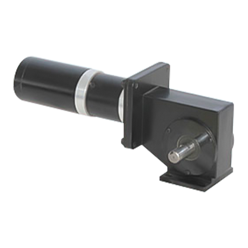
Worm Gear Motor Explained: Why This Compact Powerhouse Is Used Everywhere
Jul 10,2026
June birthday, growing towards the sun | The June employee birthday party of Dongzheng Electric Machinery came to a warm conclusion
Jun 05,2026A worm gear motor puts a lot of torque into a small space, changes the output direction by 90 degrees, and in many configurations prevents the load from back-driving the gearbox when power is off. Those three things together explain why worm gear motors show up everywhere from conveyor systems and gate operators to elevator drives and packaging machinery. They are not the right answer for every application—efficiency and thermal limits matter—but for the situations where they fit, nothing else does the job as compactly or as cost-effectively. This guide covers how a worm gearmotor works, what determines its performance, how to select the right one, and where it does and doesn't make sense against competing gear technologies.
Content
A worm gear motor combines an electric motor with a worm gearbox in a single integrated unit. The gearbox consists of two main components: the worm, which is a hardened steel shaft machined with a helical thread resembling a screw, and the worm wheel (also called the worm gear), which is a toothed wheel typically made from bronze or cast iron that meshes with the worm's threads. The two shafts are oriented at 90 degrees to each other and do not intersect—the worm runs alongside the wheel, with its threads engaging the wheel's teeth at a tangential contact point.
When the motor drives the worm shaft, the helical threads slide across the face of the worm wheel teeth, pushing the wheel to rotate. Because one full rotation of the worm advances the wheel by only the number of starts (thread starts) on the worm, the speed reduction per revolution is dramatic. A single-start worm meshing with a 40-tooth wheel produces a 40:1 reduction in one compact stage. This is the central mechanical advantage of the worm gear configuration: very high reduction ratios—from 5:1 up to 100:1 in a single stage—in a package that requires no more space than the gearbox housing itself.
The 90-degree shaft orientation is another defining characteristic. The motor input shaft runs parallel to the worm, and the output shaft extends from the worm wheel in a perpendicular direction. This right-angle drive geometry is extremely useful in machine layouts where the motor and the driven load cannot be coaxially arranged, and it eliminates the need for a separate bevel gear stage to achieve the same orientation change.
The reduction ratio of a worm gearbox is determined by dividing the number of teeth on the worm wheel by the number of starts (thread leads) on the worm. A worm with one start and a 60-tooth wheel gives 60:1. A two-start worm with the same wheel gives 30:1. The number of starts does not change the gear ratio arithmetic alone—it also directly affects efficiency and the self-locking behavior of the gearbox.
Single-start worms produce the highest reduction ratios and the strongest tendency toward self-locking, but they are also the least efficient because the shallow lead angle creates high sliding friction at the mesh point. Multi-start worms (two, three, or four starts) have steeper lead angles, which reduces sliding friction and improves efficiency, but they achieve lower reduction ratios per stage and are less likely to self-lock under load. The practical sweet spot for most industrial worm drive applications—where the goal is a meaningful reduction ratio combined with acceptable efficiency—tends to fall between 30:1 and 50:1 using a two-start worm, which keeps efficiency above 75% while the package remains compact.
Standard ratio ranges in commercial worm gear motors typically step through values such as 5:1, 7.5:1, 10:1, 15:1, 20:1, 25:1, 30:1, 40:1, 50:1, 60:1, 80:1, and 100:1. These correspond to specific worm and wheel combinations and are available as catalog items from most major gearmotor suppliers. Ratios outside this standard range require custom gear cutting and significantly increase cost and lead time.
Worm gearbox efficiency is more variable—and more frequently misread—than almost any other drive component specification. The fundamental issue is that the worm-wheel interface relies on sliding contact rather than the rolling contact used by helical or spur gears. Sliding friction is inherently higher than rolling friction, which means worm gearboxes convert a measurable portion of input power into heat rather than useful output torque.
The efficiency range for worm gearboxes spans approximately 50% to 90%, with the specific value depending primarily on the reduction ratio (and the resulting lead angle), plus lubricant type, operating temperature, and run-in condition. A 5:1 worm gearbox with a steep lead angle may achieve 85–90% efficiency under full load. A 60:1 unit with a very shallow lead angle may only achieve 40–60%. By contrast, helical gearboxes typically achieve 96–99% efficiency per stage, and planetary gearboxes achieve 95–97%.
The practical consequence of lower efficiency is heat generation. A worm gearmotor running at 60% efficiency on a 1.5 kW input is dissipating 600 W as heat within the gearbox housing. For intermittent-duty applications this is manageable—the housing absorbs heat during operation and dissipates it during rest periods. For continuous-duty applications at high load, this heat balance becomes the sizing constraint, not just the torque rating. Many manufacturers publish thermal power ratings alongside mechanical torque ratings for exactly this reason. Selecting a worm gearmotor based purely on its torque capacity without checking the thermal rating for the intended duty cycle is the most common cause of premature failure in these units.
Where efficiency is important but the other advantages of worm gearing—compact right-angle geometry, high single-stage ratio, self-locking—are still needed, a helical-worm combination gearbox is the practical solution. These units add a helical primary reduction stage before the worm stage. The helical stage handles a portion of the total ratio at high efficiency, and the worm stage handles the remainder. The net result is 10–30% better efficiency than a pure worm gearbox at the same total ratio, combined with lower heat generation and longer continuous-duty capability. The self-locking property is typically retained in higher-ratio configurations because the worm stage still dominates the friction balance.

Self-locking is the property that prevents the worm wheel from back-driving the worm when external load is applied to the output shaft and the motor is not powered. It occurs when the lead angle of the worm is shallow enough that the friction between the worm and wheel faces is greater than the tangential force that the load could generate at the mesh point. In practice, this typically occurs at reduction ratios above 40:1 in single-start worm gearboxes, though the exact threshold depends on the materials, surface finish, lubricant, and condition of the gear faces.
Self-locking is genuinely useful. In a gate operator, a conveyor holding position on a slope, or a positioning actuator, the ability of a worm gearmotor to hold its output shaft stationary without continuous motor power eliminates the need for a separate parking brake in many designs. This simplifies the system and reduces cost.
However, self-locking should not be relied upon as a safety mechanism in applications where an uncontrolled load movement would injure personnel or damage equipment. Several real-world factors can compromise self-locking behavior: gear wear over service life reduces the friction that maintains the lock, vibration can induce incremental back-driving even in nominally self-locking geometries, and efficiency improvements from synthetic lubricants can push borderline ratios into back-drivable territory. For lifting equipment, hoists, or any application where load retention has safety implications, a mechanical brake or secondary locking device is required regardless of the gearbox self-locking specification.
The combination of compact right-angle geometry, high single-stage reduction, self-locking tendency, quiet operation, and low cost makes worm gearmotors the preferred choice across a wide range of industries and machine types.
Conveyor and material handling systems:Worm gearmotors are among the most common drives on flat belt conveyors, roller conveyors, and screw feeders. The hollow-bore output option allows the gearbox to mount directly on the conveyor drive shaft without a separate coupling or shaft support.
Gate and door operators:Automatic gates, shutters, and roll-up doors use worm gearmotors for their self-locking property—the gate stays in position when power is removed without needing a separate brake.
Elevators and platform lifts:Smaller residential and commercial elevators use worm gearmotors for their compact form factor and holding capability. Industrial scissors lifts and platform lifters use similar configurations.
Packaging and food processing machinery:The quiet operation and compact right-angle drive of worm gearmotors suits the space constraints and noise sensitivity of food processing and packaging environments. Wash-down rated housings with sealed bearings are available for hygienic applications.
Mixers and agitators:Industrial mixers for chemical processing, water treatment, and food production use worm gearmotors to drive slow-speed paddle and impeller assemblies under high continuous torque.
Robotics and automation:Worm gearmotors are used in robotic joints, rotary tables, and indexing mechanisms where the combination of position holding and compact geometry is valuable. Worm gear stepper motors offer discrete positional control with self-locking in precision automation systems.
Automotive and marine accessories:Windshield wipers, powered seat adjusters, truck winches, and boat lift mechanisms use small DC worm gear motors for compact, reliable actuation with inherent position holding.
Choosing between a worm gearmotor and a helical inline or planetary gearmotor requires honest assessment of which performance parameters matter most for the specific application. There is no universally superior choice—each gear type has a domain where it wins clearly.
|
Parameter |
Worm Gear Motor |
Helical / Inline |
Planetary |
|
Efficiency |
50–90% (ratio-dependent) |
96–99% per stage |
95–97% per stage |
|
Single-stage ratio range |
5:1 to 100:1 |
3:1 to 10:1 per stage |
3:1 to 10:1 per stage |
|
Output shaft direction |
90° right-angle |
Parallel (inline) |
Parallel (inline) |
|
Self-locking |
Yes (at higher ratios) |
No |
No |
|
Noise level |
Low (~65 dB) |
Moderate (~75–85 dB) |
Low–moderate |
|
Shock load capacity |
High (up to 300%) |
Moderate (~200%) |
Moderate–high |
|
Unit cost |
Low |
Moderate |
Higher |
|
Continuous duty suitability |
Moderate (thermal limits) |
Excellent |
Excellent |
Choose a worm gearmotor when you need a right-angle drive, a high single-stage ratio, quiet operation, or a self-locking hold capability, and the application is intermittent-duty or the efficiency trade-off is acceptable at the required ratio. Choose a helical inline gearmotor when the application is continuous-duty with high load, efficiency is critical for energy cost or thermal management, or when multiple stages at moderate ratios are acceptable. Choose a planetary gearmotor when you need high torque density, precision positioning, low backlash, and are willing to pay the cost premium.
Getting the selection right requires working through a specific sequence of parameters. Starting from the wrong end—picking a motor power and then finding a gearbox to fit—is the most common cause of oversized or undersized units.
Calculate the torque needed at the driven shaft from the actual load characteristics—force, radius, efficiency of downstream transmission elements, and the required safety factor. For conveyors, a service factor of 1.5 to 2.5 is typical depending on starting conditions and potential jam loads. For smooth continuous loads like mixers, a service factor of 1.25 is often sufficient. The gearbox output torque rating must exceed the calculated requirement including the service factor. Do not size on average torque alone—peak starting torque and shock load torque determine whether the gearbox survives.
Divide the motor speed (typically 1400 or 2800 RPM at 50 Hz, or 1750/3500 RPM at 60 Hz) by the required output speed to get the nominal ratio. Then match this to the nearest available standard ratio from the catalog. Slight mismatches between calculated and available ratios are normal and handled by the downstream transmission or by adjusting motor frequency via VFD if speed precision is needed.
Once a candidate gearbox is identified by torque and ratio, check its thermal power rating (S1 continuous duty rating) against the actual operating power. If the application runs continuously at or near full load, the thermal rating must exceed the input power—not just the mechanical torque capacity. Many worm gearboxes have mechanical torque capacities significantly above their thermal limits. Exceeding the thermal rating leads to lubricant breakdown and early failure, even if the gears themselves are not mechanically overloaded.
Worm gearmotors are available in several standard mounting configurations that need to match the machine layout:
Foot mount (base mount):Four mounting feet on the housing for bolting to a flat frame. The most common and flexible option for general industrial use.
Flange mount:A machined output flange for direct mounting to a machine structure. Common in packaging and indexing equipment.
Hollow bore (hollow shaft) output:The output is a hollow bore that slides directly over a driven shaft, eliminating a separate coupling and shaft support. Standard for conveyor head shaft drives and agitator drives.
IEC motor flange input (B5/B14):Accepts standard IEC-frame motors directly without a separate coupling adapter, keeping the gearmotor package compact and well-aligned.
Mounting orientation also affects oil level inside the gearbox. A unit designed for horizontal input shaft operation will have an incorrect oil level if mounted with the input shaft vertical. Always verify that the selected unit's lubrication is rated for the intended mounting orientation, or specify the orientation to the supplier so the correct oil fill quantity is provided.
Standard worm gearboxes use an oil bath lubrication system with oil change intervals typically specified at 5,000 to 10,000 operating hours or annually, whichever comes first. Synthetic oils—particularly polyalphaolefin (PAO) gear oils—provide significantly better lubricity than mineral oils in worm gear applications, which reduces friction, improves efficiency, generates less heat, and extends oil life. Some compact and fractional-frame worm gearmotors use sealed grease lubrication for life—these require no oil changes but have limited thermal capacity and are best suited for intermittent or light continuous duty. Specifying synthetic lubricant from the outset is strongly recommended for any worm gearmotor running more than one shift per day.
Your email address will not be published. Required fields are marked *
Tel: +86 0579-86817938-836
Phone: +86 15258922705
E-mail: [email protected]
Add: No.2 Zengping Rd., Dongyang, Zhejiang, China
You can contact to me using this form.
Copyright © Zhejiang Dongzheng Motor Co.,Ltd. All Rights Reserved.
 DC Gear Motor Manufacturers