


 English
 русский
 日本語
日本語 Español
 Deutsch
 中文简体
中文简体Product Consultation
Your email address will not be published. Required fields are marked *




DC Gear Motors Guide: Types, Applications & Selection Tips
Jul 16,2026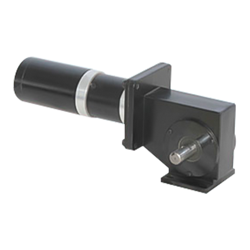
Worm Gear Motor Explained: Why This Compact Powerhouse Is Used Everywhere
Jul 10,2026
June birthday, growing towards the sun | The June employee birthday party of Dongzheng Electric Machinery came to a warm conclusion
Jun 05,2026A standard stepper motor is already a remarkably useful device—it moves in precise increments, holds its position without a brake, and requires no feedback sensor for basic positioning. But there is a class of applications where the stock motor falls short: loads that need more torque than the motor can generate, loads with high inertia that resist acceleration, or positioning tasks where the native 1.8-degree step angle is simply not fine enough. A geared stepper motor solves all three of these problems at once by attaching a gearbox directly to the motor shaft. The result is a compact, integrated actuator that multiplies torque, reduces speed, improves resolution, and tames difficult inertia ratios—without changing a single line of control code. This guide explains how geared stepper motors work, what the available gear types offer, how to select the right configuration, and where these motors perform best.
Content
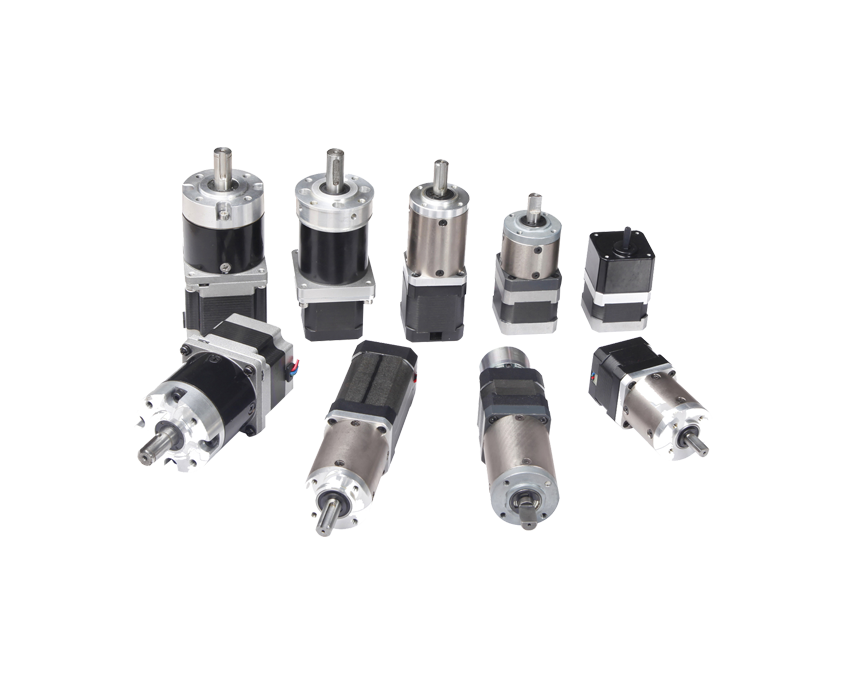
A geared stepper motor is an integrated unit consisting of a stepper motor—typically a two-phase bipolar hybrid stepping motor—combined directly with a gearbox attached to its output shaft. The gearbox is engineered and aligned at the factory, so the motor and gearhead share a single mounting flange and present a unified mechanical interface to the machine. The motor shaft drives the gearbox input; the gearbox output shaft delivers motion to the load at a reduced speed and proportionally increased torque.
The stepper motor portion operates identically to a standalone stepper: the driver sends step and direction pulses, the motor advances by one step (or microstep) per pulse, and the position is tracked open-loop by counting pulses. The gearbox does not alter this control behavior—it simply transforms the motion at its output. Every step the motor takes advances the output shaft by one step angle divided by the gear ratio. A 1.8-degree motor (200 full steps per revolution) with a 10:1 gearbox produces an effective step angle of 0.18 degrees and 2,000 steps per output revolution. This multiplication of resolution is one of the most practically valuable properties of the geared stepper motor configuration.
Torque transformation follows the same ratio. Output torque equals the motor's holding torque multiplied by the gear ratio and the mechanical efficiency of the gearbox. A NEMA 17 motor with 0.5 Nm holding torque and a 10:1 gearbox at 90% efficiency delivers approximately 4.5 Nm at the output shaft—equivalent in output to a much larger and more expensive ungeared stepper. This torque multiplication is why a NEMA 17 or NEMA 23 geared stepper motor can often replace a NEMA 34 ungeared motor, saving board space and weight in the machine.
One of the most important—and least discussed—reasons to add a gearbox to a stepper motor is inertia matching. When a stepper motor drives a load, the ratio of load inertia to rotor inertia determines how well the motor can accelerate, decelerate, and stop precisely. If the load inertia is much larger than the rotor inertia, the motor struggles to control the load during dynamic moves, resulting in overshoot (more steps taken than commanded), undershoot (fewer steps taken), or lost steps—all forms of positioning error that defeat the purpose of using a stepper in the first place.
A gearbox reduces the load inertia reflected back to the motor by the square of the gear ratio. A 10:1 gearbox reduces reflected load inertia by a factor of 100. This means a motor that could not reliably control a high-inertia load directly can suddenly do so with confidence through a gearbox. The practical threshold most designers work within is a load-to-rotor inertia ratio of 10:1 or less. At higher ratios, positioning accuracy and dynamic performance degrade. If the calculated ratio without gearing exceeds this threshold, adding a gearbox is often the correct engineering response—more effective and less expensive than simply specifying a larger motor.
There is also a resonance benefit. Ungeared stepper motors operating at low speeds can exhibit mid-frequency resonance—a vibration and instability caused by the interaction between the step frequency and the motor's natural resonant frequency. Because a geared stepper motor runs its internal motor at a higher speed (speed multiplied by the gear ratio) to produce the same output speed, the motor operates further along its speed-torque curve, away from the low-speed resonance zone. This produces smoother, more stable motion at the output shaft than an ungeared motor running at the same final speed.
Not all gearboxes suit stepper motor applications equally. Because stepper motors are used for positioning—with bidirectional moves, dynamic load changes, and precise stop-and-hold requirements—the gearbox must handle backlash, torsional stiffness, and efficiency carefully. Three gear types dominate the stepper motor gearhead market: planetary, spur, and worm. Each has a distinct performance profile.
Planetary gearboxes are the most widely used gearhead type for precision geared stepper motors. A planetary stage consists of a central sun gear driven by the motor shaft, multiple planet gears that orbit the sun while meshing with a fixed outer ring gear, and a carrier that transfers the planet gear motion to the output shaft. Because torque is distributed across multiple planet gear contacts simultaneously, planetary gearboxes achieve high torque density and high torsional stiffness in a compact, coaxial package—the output shaft runs along the same axis as the motor shaft.
For NEMA 17 motors, precision planetary gearboxes are available with backlash as low as 15 arc-minutes in economy grades and under 3 arc-minutes in high-precision grades. Gear ratios typically range from 3.7:1 up to 100:1 in a single-stage unit, with two-stage configurations extending this to 369:1. Efficiency per stage is typically 90–97%, which means the torque multiplication is close to theoretical and heat generation is modest compared to worm gear alternatives. Planetary gearheads for NEMA 23 motors deliver output torques up to 15 Nm and beyond; NEMA 34 and NEMA 42 planetary geared stepper motors reach 120 Nm or higher.
Spur gear gearheads use a series of meshing parallel-shaft spur gears to achieve the required reduction. They are simpler and less expensive than planetary units, and they offer higher efficiency (often 95% or above) because each gear mesh involves rolling rather than sliding contact. However, spur gearheads are larger in diameter for the same ratio and torque rating, they have more backlash than precision planetary units (typically 1 to 3 degrees), and they are not coaxial—the motor and output shafts may be offset. For cost-sensitive applications with moderate torque requirements, simple drive layouts, and no tight backlash specification, spur gear stepper motors are an economical choice. They are commonly used in 3D printers, light CNC applications, and consumer-grade automation where a few degrees of backlash does not significantly affect positioning accuracy.
Worm gear stepper motors combine the precise step-based control of a stepper with the high ratio, right-angle drive, and self-locking capability of a worm gearbox. Ratios from 17:1 up to 500:1 are available in standard products, making worm-geared steppers suitable for applications requiring very slow output speeds without multiple gear stages. The self-locking property—where the load cannot back-drive the worm—eliminates the need for a holding brake in many vertical-axis or load-holding applications. The trade-offs are lower efficiency (40–80% depending on ratio), higher heat generation at continuous duty, and significantly more backlash than planetary units. Worm gear stepper motors are well suited for gate actuators, linear lifting stages, indexing turntables, and other applications where position holding under load is required and the duty cycle is intermittent.

|
Property |
Planetary |
Spur |
Worm |
|
Typical ratio range |
3:1 – 100:1 per stage |
3:1 – 50:1 |
17:1 – 500:1 |
|
Backlash (typical) |
3–70 arc-min |
1–3 degrees |
Moderate–high |
|
Efficiency |
90–97% per stage |
~95% |
40–80% |
|
Output shaft direction |
Coaxial (inline) |
Inline or offset |
90° right-angle |
|
Self-locking |
No |
No |
Yes (most ratios) |
|
Torsional stiffness |
High |
Moderate |
Moderate–low |
|
Relative cost |
Moderate–high |
Low |
Low–moderate |
|
Best use case |
Precision positioning, automation |
Light loads, cost-sensitive |
High ratio, load holding |
Geared stepper motors are standardized around NEMA frame sizes, which define the motor faceplate dimensions and mounting hole pattern. The NEMA designation does not specify electrical or torque performance—those vary by motor winding and length—but it does define the physical form factor, making it straightforward to specify gearheads that fit standard motor bodies.
The combination of open-loop step-based control, high output torque, fine effective resolution, and compact integrated packaging makes geared stepper motors the preferred actuator in a wide range of industries.
Geared stepper motors are standard actuators in Cartesian robots, gantry systems, rotary indexers, and pick-and-place machines. The planetary geared stepper motor at NEMA 23 or NEMA 34 size provides the torque and resolution needed for precise axis positioning without the cost of a servo system. The self-contained step-and-direction interface simplifies controller design—most PLCs and motion controllers can drive a stepper driver directly without additional feedback infrastructure.
Fluid dispensing systems, syringe pumps, analytical instrument sample stages, and diagnostic equipment use compact geared stepper motors—often NEMA 11 or NEMA 17 with planetary gearboxes—where precise, repeatable positioning in a small package is critical. The ability to hold position without continuous power draw is valuable in battery-operated or low-heat instruments where motor energization needs to be minimized during idle periods.
Extruder drives and Z-axis leadscrew drives in 3D printers commonly use NEMA 17 planetary geared stepper motors to multiply the torque available for pushing filament or lifting the print head against gravity. The improved resolution from the gear ratio also enables finer layer height control at the leadscrew without switching to a higher-microstep driver configuration.
Indexing conveyors, label applicators, cap torquers, and filling heads in packaging lines use geared stepper motors for their repeatable, programmable positioning and their ability to hold position between moves without a separate parking brake. Worm-geared stepper motors are used specifically in vertical filling and capping stations where the load must not back-drive when the motor is de-energized.
Worm gear stepper motors are well suited for automated gate, door, and valve actuators where the self-locking property keeps the mechanism in position without continuous motor holding current. The high reduction ratio allows a small motor to generate the torque needed to move heavy gates or overcome spring-loaded valve mechanisms without an oversized motor body.
Selecting a geared stepper motor correctly requires working through several interdependent parameters in a specific order. Skipping steps—particularly the inertia check and the thermal duty cycle evaluation—leads to a motor that works on the bench but fails in service.
Before looking at any motor datasheet, establish the application requirements: required output torque (including a service factor for peak loads and acceleration), required output speed in RPM, move profile (acceleration time, travel, deceleration time), and duty cycle (percentage of time the motor is actively moving versus holding or de-energized). These parameters determine every downstream selection decision. Output torque and speed together define the mechanical power requirement; duty cycle determines whether thermal ratings become binding constraints.
The gear ratio should be selected to place the motor operating speed in the upper portion of its usable speed range—typically 200 to 600 RPM for most hybrid stepper motors—where the torque-speed curve is still reasonably flat. Running the motor at very low speeds (below 100 RPM without gearing) puts it in the resonance-prone zone and delivers less stable motion than running it faster through a gearbox. Once the target motor speed is determined, the ratio is simply the motor speed divided by the required output speed. Verify that the resulting output torque (motor holding torque × gear ratio × efficiency) meets the load requirement including the service factor. If it does not, increase the motor frame size or increase the ratio.
Calculate the load inertia (including the gearbox output shaft, coupling, and all mechanical components between the gearbox output and the final load) and divide by the rotor inertia of the selected motor. The reflected load inertia (load inertia divided by the gear ratio squared) is what matters for the motor. Aim to keep the reflected inertia-to-rotor inertia ratio below 10:1 for stable dynamic performance. If the ratio exceeds this, either increase the gear ratio or select a motor with a larger rotor inertia. Closed-loop geared stepper motors with encoder feedback can tolerate higher inertia ratios than open-loop systems, because the controller can detect and correct for lost steps.
Backlash is the angular play at the output shaft when the motor reverses direction—the output shaft does not move until the gear mesh clearance is taken up. In applications where the load always moves in one direction (dispensing pumps, one-direction conveyors), backlash has no practical effect. In bidirectional positioning applications, backlash directly limits repeatable positioning accuracy. Economy planetary gearboxes offer backlash around 50 arc-minutes; precision planetary grades bring this down to 15 arc-minutes; high-precision grades achieve 3 arc-minutes or less. Specify the tightest backlash grade that the application genuinely requires—not the tightest available—because high-precision gearboxes carry a significant cost premium.
Verify that the selected gearbox output shaft diameter, keyway specification, maximum allowable radial load, and maximum allowable axial load are compatible with the coupling or driven component. Gearboxes for stepper motors have defined permissible radial and axial load ratings that, if exceeded, accelerate bearing wear and reduce gearbox life. If the application imposes significant overhung (radial) loads—such as a pinion gear or belt pulley mounted directly on the output shaft without additional support—ensure the gearbox bearing rating accommodates the load at the operating speed.
Your email address will not be published. Required fields are marked *
Tel: +86 0579-86817938-836
Phone: +86 15258922705
E-mail: [email protected]
Add: No.2 Zengping Rd., Dongyang, Zhejiang, China
You can contact to me using this form.
Copyright © Zhejiang Dongzheng Motor Co.,Ltd. All Rights Reserved.
 DC Gear Motor Manufacturers