


 English
 русский
 日本語
日本語 Español
 Deutsch
 中文简体
中文简体Product Consultation
Your email address will not be published. Required fields are marked *




DC Gear Motors Guide: Types, Applications & Selection Tips
Jul 16,2026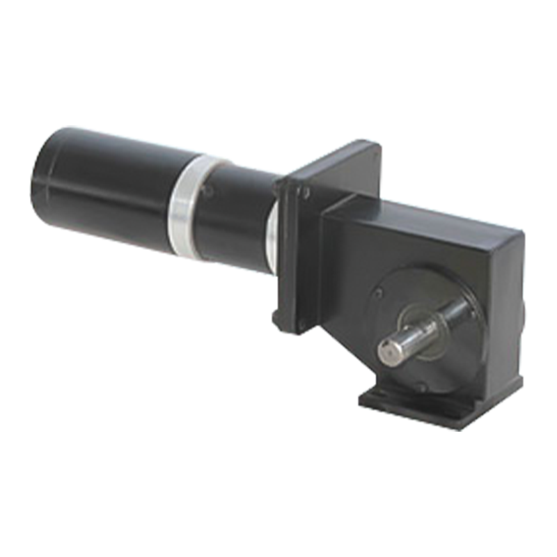
Worm Gear Motor Explained: Why This Compact Powerhouse Is Used Everywhere
Jul 10,2026
June birthday, growing towards the sun | The June employee birthday party of Dongzheng Electric Machinery came to a warm conclusion
Jun 05,2026Content
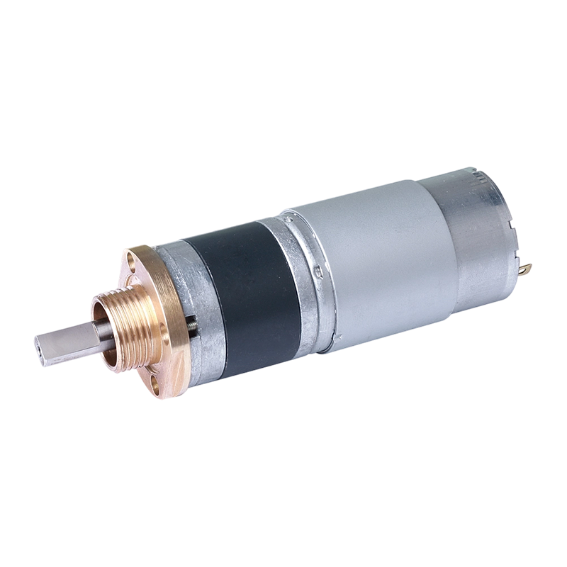
A DC gear motor is a direct-current electric motor paired with a mechanical gearbox in a single integrated unit. The motor itself spins fast — often 3,000 to 15,000 RPM at rated voltage — but most real-world applications need slow, controlled movement with substantial turning force. The gearbox solves this by trading speed for torque through a series of meshing gears. The result is an output shaft that turns far more slowly than the motor's rotor, but with proportionally higher torque available at the shaft.
Without the gearbox, a small DC motor can spin a fan blade easily but struggles to lift a load, drive a conveyor belt, or turn a valve. With a gear reduction of, say, 100:1, the same motor that produces 5 mN·m of free-running torque now delivers approximately 500 mN·m at the output — minus losses from gear mesh friction, typically 5–20% depending on gear type and lubrication. That multiplication of torque, combined with the compact integration of motor and gearbox into one assembly, is why DC geared motors are among the most widely specified motion components in industrial, commercial, and consumer applications.
The gearbox design has a larger impact on performance, size, efficiency, and noise than almost any other design variable. Four configurations dominate the market.
Spur gears have straight teeth cut parallel to the shaft axis. They are the simplest and least expensive gear type to manufacture, which makes spur gear DC motors the default choice for cost-sensitive applications. Their main weakness is noise: because the full tooth width engages simultaneously at each mesh contact, spur gears produce a characteristic clatter at high speed. Efficiency is good — typically 95–98% per stage — and they handle moderate radial loads well. Spur gear motors are common in printers, toys, vending machines, and light-duty actuators where quiet operation is not a priority.
A planetary gearbox arranges multiple "planet" gears around a central "sun" gear, all contained within a ring gear. Because the load is shared across several planet gears simultaneously, a planetary DC gear motor delivers very high torque density in a compact, coaxial package. The output shaft is aligned with the motor shaft, which simplifies installation in space-constrained layouts. Planetary gearboxes are stiffer and more precise than spur or worm types, making them the preferred choice for robotics, automated guided vehicles (AGVs), electric screwdrivers, and any application that demands high torque, tight positional accuracy, and a long service life. The tradeoff is cost: planetary gearboxes are significantly more expensive to produce than spur or helical types at the same torque rating.
A worm gearbox uses a screw-like worm shaft that meshes with a worm wheel at a 90-degree angle. This configuration achieves very high reduction ratios in a single stage — commonly 5:1 to 100:1 — and provides a natural self-locking characteristic: when the motor stops, the load cannot back-drive the gearbox. This makes worm gear DC motors ideal for applications where the load must hold position without power, such as garage door openers, stage lifts, hospital bed actuators, and security barriers. The main limitation is efficiency: worm gear mesh friction is high, with typical single-stage efficiency ranging from 50–90% depending on lead angle, with higher ratios being progressively less efficient. Worm gear motors also produce significant heat under continuous high-load duty cycles.
Helical gears have teeth cut at an angle to the shaft axis, so contact between teeth is gradual and progressive rather than abrupt. This dramatically reduces noise and vibration compared to spur gears and slightly improves load capacity due to the larger effective contact area. Helical DC gear motors are common in applications that require quieter operation — conveyor drives, packaging machinery, and medical equipment. Helical-bevel combinations allow the output shaft to be offset at 90 degrees to the motor, similar to a worm drive but with higher efficiency (typically 94–97% per stage). The increased axial thrust generated by helical gear mesh requires bearings that can handle this load, which adds slightly to unit cost.
The DC motor element itself comes in two fundamental architectures, and the choice between them affects cost, maintenance requirements, speed range, and service life significantly.
|
Feature |
Brushed DC Gear Motor |
Brushless DC Gear Motor (BLDC) |
|
Commutation Method |
Mechanical (carbon brushes + commutator) |
Electronic (ESC or motor driver) |
|
Typical Service Life |
500–3,000 hours (brush wear limited) |
10,000–20,000+ hours |
|
Control Complexity |
Simple — voltage or PWM direct |
Requires dedicated BLDC driver/ESC |
|
Efficiency |
75–85% typical |
85–95% typical |
|
Noise & EMI |
Higher (brush arcing generates EMI) |
Lower |
|
Unit Cost |
Lower |
Higher (motor + driver) |
|
Typical Applications |
Toys, appliances, light automation |
Robotics, AGVs, medical devices, EVs |
For prototyping or low-duty intermittent applications, a brushed DC gear motor driven by a simple L298N or TB6612FNG H-bridge is the fastest, cheapest route to a working system. For anything that runs continuously, operates in a harsh environment, or must last years in the field without maintenance, a brushless DC gear motor — despite its higher upfront cost and additional driver electronics — almost always delivers better total cost of ownership.
DC gear motor datasheets can be dense, but five parameters determine whether a motor will work in your application. Understanding each one prevents the most common selection mistakes.
DC gear motors are designed for a specific supply voltage — most commonly 6V, 12V, 24V, or 48V in industrial and hobby applications. Operating a motor significantly above its rated voltage accelerates brush wear in brushed types, overheats windings, and shortens bearing life. Operating below rated voltage reduces available torque and may cause the motor to stall under load. For battery-powered systems, match the motor's rated voltage to the nominal battery pack voltage at mid-charge, not at full charge, to avoid overvoltage at the top of the charge cycle. A 12V DC gear motor run from a freshly charged 3S LiPo (12.6V) is marginally acceptable; running it from a 4S pack (16.8V) will destroy it quickly.
The no-load speed is the output shaft RPM when the motor is running at rated voltage with zero applied torque. Under actual load, speed drops — typically by 10–20% at rated (continuous) torque, and by up to 50% at peak stall torque. When calculating whether a DC geared motor can move a load at the required speed, always use the loaded speed at your expected torque operating point, not the no-load figure. Manufacturers sometimes only list no-load speed and stall torque; the loaded operating point falls roughly in the middle of the speed-torque curve.
Rated torque (also called continuous torque) is the maximum torque the motor can deliver indefinitely without overheating. Stall torque is the peak torque produced when the shaft is held stationary — typically 5–10 times the rated torque for a brushed DC gear motor. Stall torque is useful for sizing intermittent peak loads (the force needed to break a stuck valve free, for example), but operating continuously at or near stall will overheat the motor rapidly. Select a motor whose rated torque is at least 20–30% above your application's expected continuous load torque. This safety margin accounts for friction variation, voltage sag, and temperature derating.
The gear ratio expresses how many motor shaft revolutions produce one output shaft revolution. A ratio of 50:1 means the output turns once for every 50 motor turns. Higher gear ratios produce lower output speed and higher output torque. However, very high ratios introduce more gear stages, which increases friction losses and backlash — the small amount of free play in the output shaft when direction reverses. For positioning applications, backlash is a critical specification: planetary gearboxes typically offer 0.5–3 arc-minutes of backlash in precision grades, while economy spur gearboxes may have 1–5 degrees of backlash, which is unacceptable for anything requiring repeatable positioning.
Duty cycle describes the percentage of time a motor operates versus rests within a given cycle period. A motor rated for S1 (continuous duty) can run indefinitely at rated load without overheating. S2 (short-time duty) and S3 (intermittent periodic duty) ratings allow higher peak power levels because the motor cools during the off periods. Always match the motor's duty rating to your actual operating cycle — a motor rated for 30% duty cycle will overheat and fail if run continuously, even if the torque and speed are within nameplate limits.
Voltage selection is often driven by the available power source rather than by motor preference, but understanding the typical use cases for each voltage tier helps narrow down your options quickly.
Getting motor selection right the first time avoids costly redesigns and field failures. Follow this practical framework:
Calculate the torque your application requires at the output shaft. For a wheeled robot, this means computing the force needed to accelerate the robot's mass, overcome rolling friction, and climb any inclines expected in operation. For a linear actuator, calculate the force on the lead screw and convert it to motor torque via the screw's lead and efficiency. Add a 25–50% safety margin to account for friction variation, aging, and worst-case loading scenarios. This target torque number — with the margin applied — becomes your minimum rated torque specification.
Establish the minimum and maximum output shaft speed your application needs. A conveyor that moves product at 0.5 m/s with a 50 mm diameter drive roller requires an output speed of approximately 191 RPM (0.5 / (π × 0.05) × 60). Select a motor whose no-load speed is at least 15–20% above the required loaded speed to ensure the motor isn't operating near stall under normal conditions.
Use the following decision guide to match gearbox type to application requirements:
Check that your power supply can deliver the peak current demand of the motor at stall. Stall current for a brushed DC gear motor is typically 5–10 times the no-load current. If your supply cannot source this current transiently during startup or jam conditions, add a current-limiting motor driver with adjustable current limit, or select a motor driver with adequate headroom. For brushless DC gear motors, confirm the BLDC driver's continuous and peak current ratings exceed the motor's requirements with at least 20% margin.
Standard DC gear motors are not sealed. If the motor will be exposed to dust, moisture, coolant splash, or washdown conditions, specify an IP-rated unit — IP54 for dust and splash protection, IP65 or IP67 for more demanding environments. For food processing, pharmaceutical, or marine applications, confirm that the gearbox lubricant meets applicable regulatory requirements (NSF H1 food-grade grease for food contact zones, for example). Operating temperature range is also important: standard motors are rated for 0–40°C ambient; for cold-store warehouses or outdoor installations in Northern climates, confirm low-temperature grease specifications and winding temperature ratings.
DC geared motors appear in an enormous range of products and systems. Understanding where they are commonly used helps identify appropriate reference designs and validated configurations.
|
Industry |
Application |
Typical Gear Motor Type |
|
Robotics & AGVs |
Drive wheels, joint actuation, gripper mechanisms |
Brushless planetary, 24V–48V |
|
Industrial Automation |
Conveyors, indexing tables, valve actuators |
Helical, worm, or planetary, 24V |
|
Medical Devices |
Infusion pumps, surgical tools, hospital beds |
Brushless planetary, low-backlash, 12V–24V |
|
Automotive |
Power windows, seat adjusters, sunroof drives |
Brushed worm or spur, 12V |
|
Consumer Electronics |
Camera pan/tilt, smart home actuators, printers |
Brushed spur, 5V–12V |
|
Agriculture |
Irrigation valve control, seeding mechanisms |
IP-rated worm or planetary, 12V–24V |
|
Building Automation |
HVAC dampers, blind actuators, door drives |
Brushless helical or worm, 24V |
DC gear motors are well suited to variable-speed operation because the DC motor's speed is directly proportional to applied voltage. In practice, speed is controlled by one of three methods.
PWM is the standard method for controlling brushed DC gear motors from microcontrollers, PLCs, and motor driver ICs. The driver switches the motor supply on and off at a fixed frequency — typically 1–20 kHz — and the duty cycle (the percentage of time the supply is on) determines average voltage and therefore speed. A 50% duty cycle at 12V delivers approximately 6V equivalent to the motor. PWM control is efficient because the switching transistors spend most of their time fully on or fully off, minimizing resistive losses. PWM frequencies below 1 kHz can cause audible motor whine as the armature windings vibrate at the switching frequency; frequencies above 20 kHz push this above the audible range. For brushed DC gear motors, a PWM frequency of 10–20 kHz is a common practical choice.
For applications requiring precise, consistent speed regardless of load variation — robotic platforms, tape drives, precision dispensing — a rotary encoder mounted on the motor shaft or gearbox output provides real-time speed feedback to a PID controller. The controller compares actual speed to the setpoint and adjusts PWM duty cycle to compensate. Encoders for DC gear motors are typically quadrature optical or magnetic hall-effect types, with resolutions from 6 to several thousand counts per revolution depending on precision requirements. Many DC gear motor suppliers offer integrated encoder options as standard catalog items, simplifying the hardware integration significantly.
In simple systems where load is relatively constant and speed precision is not critical, speed can be set by adjusting supply voltage with a variable DC power supply or a linear voltage regulator. This approach is the least efficient — a linear regulator dissipates the voltage drop as heat — and offers no load compensation, but it is the simplest implementation and is appropriate for test benches, manual speed adjustments, and very low-power applications where thermal dissipation in the regulator is not a concern.
Understanding what eventually causes a DC gear motor to fail helps you design systems that extend service intervals and catch problems before they cause unplanned downtime.
Your email address will not be published. Required fields are marked *
Tel: +86 0579-86817938-836
Phone: +86 15258922705
E-mail: [email protected]
Add: No.2 Zengping Rd., Dongyang, Zhejiang, China
You can contact to me using this form.
Copyright © Zhejiang Dongzheng Motor Co.,Ltd. All Rights Reserved.
 DC Gear Motor Manufacturers