


 English
 русский
 日本語
日本語 Español
 Deutsch
 中文简体
中文简体Product Consultation
Your email address will not be published. Required fields are marked *


Witnessing the Grand Event, Reflecting on Our Original Aspirations, Fulfilling Our Mission, and Embarking on a New Journey | The Company’s Party Branch Watches the Live Broadcast of the Ceremony Marking the 105th Anniversary of the Founding of the Communist Party of China
Jul 01,2026
Strengthening Industry-Education Integration · Empowering Collaborative Talent Development | Dongzheng Joins Forces with Guangsha Vocational University to Write a New Chapter in School-Enterprise Cooperation
Jul 08,2026
In the Blazing Heat of Midsummer, Embarking on a New Journey Together | Dongzheng Electric Successfully Hosts July Employee Birthday Party
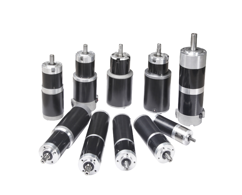
Jul 01,2026A brushed DC motor is one of the oldest and most straightforward electric motor designs still in widespread use today. It converts direct current electrical energy into mechanical rotation using a combination of a stationary magnetic field and a rotating armature winding. What distinguishes it from a brushless motor is the mechanical commutation system — a pair of carbon brushes that press against a segmented copper commutator ring mounted on the rotor shaft. As the rotor turns, the brushes make and break contact with successive commutator segments, automatically switching the current direction in the armature windings to maintain continuous rotation in one direction.
The operating principle is straightforward: current flows from the power supply through one brush, into the commutator, through the armature windings, back out through the commutator to the second brush, and returns to the supply. The current-carrying conductors in the armature sit inside a magnetic field produced either by permanent magnets or by wound field coils. The interaction between this magnetic field and the current in the armature conductors produces a force — described by the Lorentz force law — that rotates the armature. The commutator ensures that as the armature rotates, the direction of current in each winding flips at the right moment to keep the torque acting continuously in the same rotational direction.
This self-commutating design means a brushed DC motor requires only a DC supply and no external electronics to run. Apply voltage and it spins. Reverse the polarity and it spins the other way. This simplicity has kept brushed motors relevant for well over a century, even as brushless and AC motor technologies have matured.
Content
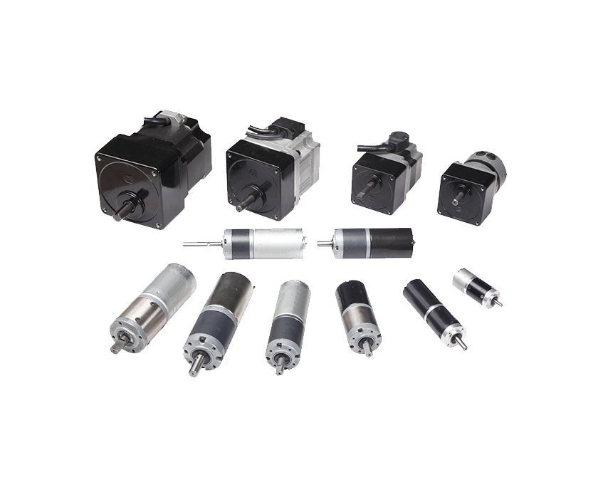
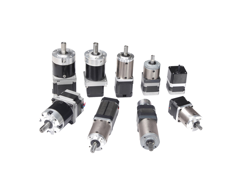
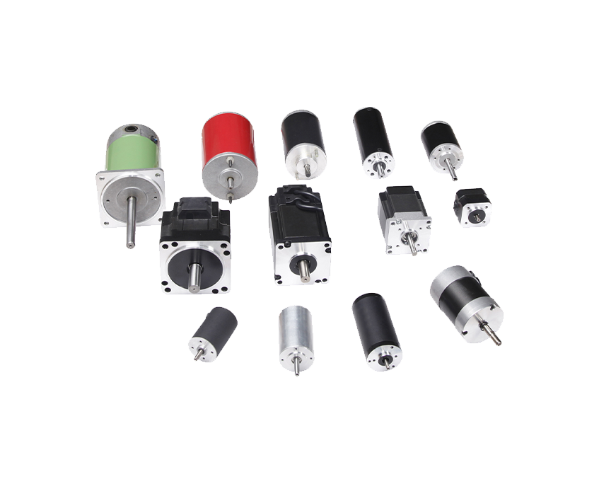
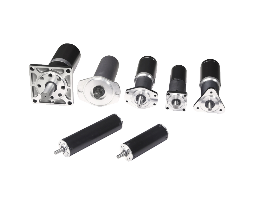
Brushed DC motors are not a single product — they are a family of designs with meaningfully different speed-torque characteristics depending on how the magnetic field is generated and how the field and armature circuits are connected.
The most common type in small and medium-power applications, the permanent magnet DC motor uses fixed magnets — typically ferrite or rare-earth neodymium — to create the stator field instead of wound coils. Because there is no separate field winding to power or control, PMDC motors are compact, efficient, and have a linear speed-torque relationship: speed drops proportionally as torque increases, making them easy to model and control. They are the standard choice for battery-powered tools, automotive actuators, small appliances, and hobby applications in the 3V–48V range. The main limitation is that the magnetic field strength is fixed by the magnets and cannot be adjusted, so speed control must be achieved through armature voltage or PWM rather than field weakening.
In a series wound DC motor, the field winding is connected in series with the armature, so the same current flows through both. This produces an extremely high starting torque — the field is strongest when armature current is highest, which occurs at low speed and stall — making series motors ideal for applications with heavy starting loads such as electric cranes, traction drives, and starter motors in internal combustion engines. The drawback is unstable speed regulation: as load decreases, current drops, the field weakens, and speed rises sharply. A lightly loaded or unloaded series motor can overspeed dangerously. For this reason, series wound brushed DC motors are almost never used in applications where the load can be completely removed during operation.
A shunt wound motor connects the field winding in parallel (shunt) with the armature across the supply voltage. Because field current depends only on supply voltage — not load current — the field remains nearly constant regardless of armature load. This gives shunt motors excellent speed regulation: speed stays relatively flat as load increases, typically varying only 5–15% from no-load to full-load. Shunt wound brushed DC motors are used in machine tools, printing presses, and industrial drives where consistent speed under varying loads is important. They also allow field weakening for above-base-speed operation by reducing field current, extending the usable speed range.
Compound wound motors combine both series and shunt field windings. The cumulative compound configuration — where both windings produce fields in the same direction — delivers a compromise between the high starting torque of a series motor and the stable speed regulation of a shunt motor. This makes compound motors well suited to applications with large, intermittent load spikes such as presses, elevators, and compressors, where the motor must handle sudden heavy loads without excessive speed drop. Differential compound winding (opposing field directions) is rarely used in practice due to unstable operating characteristics.
Coreless DC motors eliminate the iron core from the rotor, replacing it with a self-supporting cylindrical winding that rotates inside the stator's magnetic field. Removing the iron core eliminates iron losses (hysteresis and eddy current losses) and dramatically reduces rotor inertia. The result is extremely fast electrical and mechanical response — coreless brushed DC motors can accelerate to full speed in milliseconds rather than tens of milliseconds — along with very smooth, cogging-free rotation at low speeds. These properties make coreless motors the preferred choice for precision applications: medical devices, aerospace actuators, camera lens drives, pen plotters, and high-speed dental handpieces. They are typically small in physical size and operate in the 3V–24V range, with power outputs rarely exceeding a few hundred watts.
Reading a brushed DC motor datasheet confidently requires understanding what each parameter actually means in practice — and what happens when you operate outside its limits.
|
Specification |
What It Means |
Practical Note |
|
Rated Voltage |
Nominal supply voltage for continuous operation |
Operating above rated voltage shortens brush and insulation life |
|
No-Load Speed |
RPM at rated voltage with zero torque applied |
Actual operating speed will be 10–30% lower under load |
|
Stall Torque |
Maximum torque when shaft is held stationary |
Never operate continuously at stall — causes rapid overheating |
|
Rated (Continuous) Torque |
Maximum torque for indefinite continuous operation |
Add 20–30% safety margin for real-world friction and aging |
|
No-Load Current |
Current draw at rated voltage with no load |
Dominated by bearing friction and brush friction losses |
|
Stall Current |
Current at zero speed — maximum possible current draw |
Size power supply and driver to handle stall current transiently |
|
Motor Constant (Km) |
Torque per unit of input power — measure of efficiency |
Higher Km = more torque for same winding losses |
|
Back-EMF Constant (Ke) |
Voltage generated per unit of speed (V/RPM or V·s/rad) |
Numerically equal to torque constant Kt in consistent units |
|
Thermal Resistance |
Temperature rise per watt of power dissipated (°C/W) |
Use to calculate winding temperature at your operating point |
The speed-torque curve is the single most useful tool for understanding a brushed DC motor's operating envelope. For a permanent magnet brushed motor, this curve is a straight line from no-load speed (maximum speed, zero torque) to stall (zero speed, maximum torque). The motor's rated continuous operating point sits somewhere along this line, constrained by thermal limits. Any operating point beyond the continuous rating line is permissible only intermittently, for durations short enough that the winding temperature does not exceed the insulation class limit — typically 130°C for Class B insulation and 155°C for Class F.
The choice between brushed and brushless is one of the most common decisions in motor selection. Each technology has a genuine home — neither is universally superior.
|
Factor |
Brushed DC Motor |
Brushless DC Motor (BLDC) |
|
Control Complexity |
Simple — direct voltage or PWM |
Requires electronic commutation driver/ESC |
|
Service Life |
500–3,000 hours (brush-limited) |
10,000–20,000+ hours |
|
Efficiency |
75–85% typical |
85–95% typical |
|
EMI Generation |
Higher (brush arcing) |
Lower |
|
Unit Cost |
Lower motor cost |
Higher motor + driver cost |
|
Speed Range |
Good, brush contact limits very high RPM |
Excellent, no mechanical contact limit |
|
Maintenance |
Periodic brush inspection/replacement |
Essentially maintenance-free |
|
Best For |
Cost-sensitive, intermittent, simple control |
Long-life, high-efficiency, precision control |
Choose a brushed DC motor when upfront cost and control simplicity outweigh long-term maintenance concerns — for example, in consumer appliances with defined product lifespans, hobbyist robots, low-volume automation, or any application where brush replacement is an acceptable scheduled maintenance task. Choose brushless when the motor will run continuously for years, when efficiency directly impacts operating cost or battery life, when EMI must be minimized, or when the application cannot tolerate maintenance downtime — such as in medical devices, industrial automation, or sealed equipment.

One of the most practical advantages of brushed DC motors is the range of well-established, inexpensive speed control techniques available to the designer.
PWM is the dominant method for controlling brushed DC motors in modern applications. A motor driver IC — configured as an H-bridge — switches the supply voltage to the motor on and off at a fixed frequency, typically 10–20 kHz. The average voltage delivered to the motor, and therefore its speed, is determined by the duty cycle: a 75% duty cycle at 12V delivers approximately 9V equivalent. The H-bridge configuration uses four switching transistors arranged so that the motor can be driven in both directions by reversing the active pair, enabling bidirectional operation with a single driver chip. Common H-bridge ICs include the L298N (up to 2A per channel), the TB6612FNG (1.2A continuous, favored for microcontroller projects due to its logic-level compatibility), and the DRV8833 (1.5A, compact footprint, built-in current limiting). For higher-power brushed motors, discrete MOSFET H-bridges or dedicated motor driver modules rated at 10A, 20A, or more are available.
Open-loop PWM control sets motor speed by setting duty cycle, but the actual shaft speed varies with load — as load increases, speed drops. For applications requiring precise, consistent speed regardless of load variation, a feedback sensor closes the control loop. A quadrature encoder mounted on the motor shaft or output provides position and speed data to a PID controller running on a microcontroller or dedicated motion controller. The PID algorithm compares measured speed to the setpoint and adjusts duty cycle in real time to compensate. This approach is standard in CNC machines, robotic joints, and any system where position and velocity accuracy matter. Magnetic encoders are preferred in dusty or vibration-prone environments; optical encoders offer higher resolution in clean environments.
For shunt and compound wound brushed DC motors, speed can also be adjusted by varying field current independently of armature voltage. Reducing field current weakens the magnetic field, which reduces back-EMF and allows the motor to spin faster for a given armature voltage — a technique called field weakening. This extends the motor's usable speed range above the base speed set by rated armature voltage, at the cost of reduced available torque. Field weakening is commonly used in industrial variable-speed drives for machine tools, winding machines, and rolling mills where a wide speed range is required.
Brushed DC motors can be braked actively without mechanical friction brakes. Dynamic braking short-circuits the motor terminals through a resistor when the drive signal is removed — the motor acts as a generator, converting kinetic energy to heat in the resistor and decelerating rapidly. Regenerative braking goes further: instead of dissipating the energy as heat, a regenerative drive returns the braking energy back to the power supply or battery. This is the standard braking method in electric vehicles, forklifts, and regenerative industrial drives, where energy recovery meaningfully extends range or reduces operating costs.
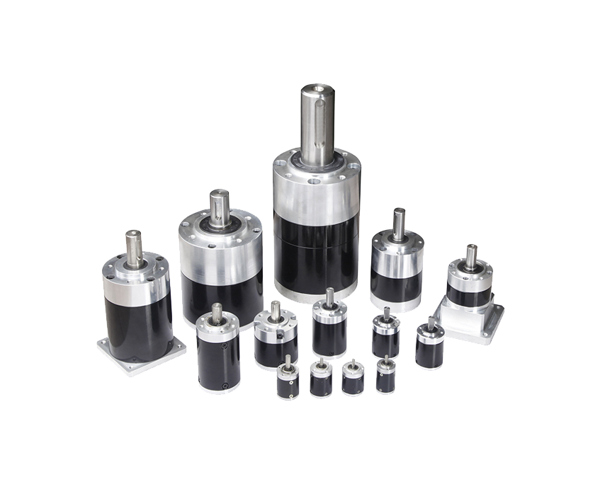
Despite competition from brushless and stepper motor technologies, brushed DC motors remain the dominant choice in a wide range of applications where their cost, simplicity, and controllability provide a decisive advantage.
The carbon brushes and commutator are the primary wear components in a brushed DC motor, and managing them correctly is the key to maximizing service life and avoiding unplanned failures.
Carbon brushes wear through a combination of mechanical abrasion against the rotating commutator surface and electrochemical erosion from the arcing that occurs each time a brush transitions between commutator segments. A thin film of copper oxide and graphite — called the patina or film — builds up on the commutator surface during normal operation and actually reduces friction and wear rate. Disrupting this film by using incorrect brushes, operating in excessively dry or humid conditions, or running the motor with significant sparking accelerates wear. Typical brush life for a brushed DC motor in continuous duty ranges from 500 hours for a lightly constructed consumer motor to 3,000 hours or more for an industrial-grade motor with high-quality graphite brushes and proper commutator surface maintenance.
The commutator surface should be smooth, cylindrical, and medium-brown in color from the healthy patina film. Grooves cut by worn brushes, flat spots from uneven wear, or black burn marks from excessive sparking all require corrective action. Light surface oxidation can be polished away with a commutator cleaning stick (a graphite stick or commutator stone) applied to the rotating commutator without disassembling the motor. Deeper grooves and out-of-round conditions require machining — turning the commutator on a lathe to restore concentricity — after which the mica insulation between commutator segments must be undercut to prevent it from riding above the copper surface. These procedures extend motor life significantly and are standard practice in industrial motor maintenance programs.
Motor selection mistakes are common and costly. This practical framework ensures you account for the parameters that actually determine whether a motor will work reliably in your application.
Your email address will not be published. Required fields are marked *
Tel: +86 0579-86817938-836
Phone: +86 15258922705
E-mail: [email protected]
Add: No.2 Zengping Rd., Dongyang, Zhejiang, China
You can contact to me using this form.
Copyright © Zhejiang Dongzheng Motor Co.,Ltd. All Rights Reserved.
 DC Gear Motor Manufacturers