


 English
 русский
 日本語
日本語 Español
 Deutsch
 中文简体
中文简体Product Consultation
Your email address will not be published. Required fields are marked *




DC Gear Motors Guide: Types, Applications & Selection Tips
Jul 16,2026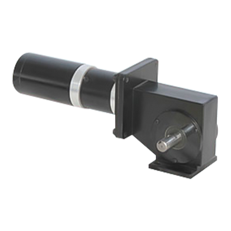
Worm Gear Motor Explained: Why This Compact Powerhouse Is Used Everywhere
Jul 10,2026
June birthday, growing towards the sun | The June employee birthday party of Dongzheng Electric Machinery came to a warm conclusion
Jun 05,2026Content
The 24V brushed DC motor has been a staple of industrial and commercial machine design for decades — and for good reason. Running on a 24-volt supply hits a practical sweet spot: it delivers enough torque and power density for demanding tasks while remaining safe enough to handle without specialized high-voltage precautions. Compared to 12V variants, a 24V brushed motor draws half the current for the same power output, which directly reduces resistive losses in wiring and allows the use of thinner, lighter gauge cable across the system.
Brushed DC motors work on a straightforward principle: current flows through stationary brushes, transfers to a rotating commutator, and energizes the armature windings in sequence. This commutation creates the rotating magnetic field that drives the shaft. Because the commutation is mechanical rather than electronic, no separate motor controller is strictly required for basic operation — applying 24V DC to the terminals makes the motor spin immediately. This simplicity is a major reason why brushed DC motors remain competitive in cost-sensitive, high-volume applications where reliability matters more than peak efficiency.
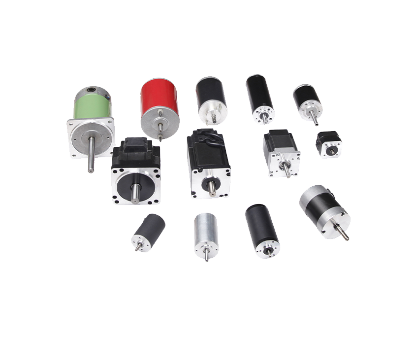
Modern 24V brushed motors are available in a wide range of frame sizes, from compact 37mm diameter gearmotors used in medical devices and robotics, all the way to large industrial brush motors producing several kilowatts for conveyor and pump applications. The technology scales well, and decades of manufacturing refinement mean that high-quality units are available at highly competitive price points compared to brushless alternatives.
Choosing the right 24V brushed DC motor starts with understanding the core nameplate specifications and what they mean in practice. Two motors with the same voltage rating can have dramatically different performance characteristics depending on their winding configuration, physical size, and intended duty cycle. Reading a datasheet correctly prevents costly mismatches between the motor and the application.
Rated power (in watts) describes the motor's sustainable output under normal operating conditions. A 24V 250W brushed DC motor, for example, delivers 250W continuously without overheating — typically drawing around 10–12A depending on efficiency. Peak or stall torque is significantly higher but should only be drawn transiently. Sustained operation at stall or near-stall current will overheat the armature windings and destroy the motor within minutes. Always size the motor so the application's average load falls within the continuous duty rating.
No-load speed (RPM) is the shaft speed when the motor runs freely with no mechanical load. As load increases, speed decreases in a roughly linear relationship — this is the speed-torque curve. Understanding where your application sits on this curve is essential. If your operating torque puts you near the stall end of the curve, the motor will run slowly, draw high current, and generate excessive heat. For most applications, the target operating point should be between 50–80% of no-load speed for good efficiency and long brush life.
Brush material has a direct impact on how long the motor lasts before maintenance is needed. Carbon brushes are the most common and offer a good balance of conductivity, low friction, and self-lubricating properties. Copper-graphite brushes handle higher current densities and are used in high-power applications. Silver-graphite brushes are reserved for precision instruments where low contact resistance and minimal electrical noise are critical. A well-designed 24V brushed motor with carbon brushes can offer brush service lives of 500 to 2,000+ hours depending on load, speed, and operating environment.
| Specification | Typical Range (24V Brushed DC) | What It Affects |
|---|---|---|
| Rated Power | 10W – 3,000W | Application sizing, heat generation |
| No-Load Speed | 500 – 10,000 RPM | Output speed, gearbox ratio selection |
| Stall Torque | 0.05 – 50+ N·m | Peak force capability |
| Rated Current | 0.5A – 150A | Driver and wiring selection |
| Efficiency | 60% – 85% | Thermal management, battery life |
| Brush Life | 500 – 3,000 hours | Maintenance interval, total cost of ownership |
The versatility of the 24V brushed motor makes it appear across a remarkably broad range of applications. The 24V supply voltage aligns well with standard industrial control systems, battery-powered equipment, and forklift auxiliary circuits — which means infrastructure and power supplies are often already available without additional conversion hardware.
In robotics, 24V brushed DC gearmotors are widely used for wheel drives, joint actuators, and conveyor mechanisms in automated guided vehicles (AGVs) and collaborative robot platforms. Their linear speed-torque relationship makes them straightforward to control with PWM-based motor drivers, and their low cost allows multi-axis systems to be built economically. Entry-level and mid-tier robot platforms from hobbyist environments to light industrial pick-and-place systems commonly rely on brushed 24V motors, particularly where the duty cycle is moderate and periodic brush replacement is acceptable.
Many electric scooters, power wheelchairs, mobility scooters, and light electric utility vehicles use 24V brushed motors for their drivetrain. The two-battery-in-series 12V configuration is a common and cost-effective way to produce a 24V system in these vehicles. Brushed motors in this context benefit from simple regenerative braking implementations and easy field-weakening for higher top-end speed. Industrial electric pallet jacks and order pickers also frequently use 24V brushed traction and pump motors due to the maturity of the technology and ease of on-site servicing by maintenance staff.
Packaging lines, labeling equipment, small conveyor belts, and assembly fixtures frequently employ 24V brushed DC motors paired with worm or planetary gearboxes for precise, low-speed torque delivery. The ability to vary speed by simply adjusting voltage or PWM duty cycle — without a sophisticated inverter — makes brushed motors attractive for OEM machine builders who want to keep their control architecture simple and their bill of materials lean. Motors in the 50–500W range dominate this segment.
Infusion pumps, surgical tools, laboratory centrifuges, and diagnostic instrument platforms often use small 24V brushed coreless DC motors — a design variant that eliminates the iron armature core for dramatically reduced rotor inertia and smoother low-speed operation. Coreless brushed motors in the 1–30W range are a preferred choice where precise positional control and fast response are needed, and where operating hours are low enough that brush wear is not a significant concern over the product's service life.

One of the most practical advantages of a brushed DC motor is how easily it can be controlled. Speed is adjusted by varying the average voltage applied to the motor — either through linear voltage adjustment or, more commonly, through Pulse Width Modulation (PWM). PWM switches the supply voltage on and off at a high frequency (typically 10–25 kHz), and the ratio of on-time to off-time (duty cycle) determines the effective average voltage. At 50% duty cycle on a 24V supply, the motor sees an average of 12V and runs at roughly half speed.
To reverse a brushed DC motor, you need to reverse the polarity of the voltage across its terminals. An H-bridge circuit — named for its shape in schematic form — uses four switching transistors arranged so that either polarity can be applied to the motor by activating different pairs of switches. H-bridge driver ICs like the L298N, DRV8833, and VNH5019 are readily available and handle motors up to 2–5A continuously in a single package, making them ideal for robotics and light automation. For higher-power 24V motors drawing 10A or more, discrete MOSFET H-bridges or dedicated industrial motor drivers are required.
For applications requiring consistent shaft speed despite varying loads — or precise positional control — a feedback device is added to the motor shaft. A quadrature encoder provides position and velocity data to a microcontroller or dedicated PID controller, which adjusts PWM duty cycle in real time to maintain the target speed or position. Many 24V brushed gearmotors are available with integrated encoders already mounted on the motor body, simplifying system integration significantly. Encoder resolutions of 12–1,024 counts per revolution (CPR) cover the range from basic speed regulation to precise multi-turn positioning.
The brushed vs. brushless debate is one of the most frequent decision points for engineers sourcing motors. Both technologies operate at 24V and can be built to similar power and torque specifications, but they differ significantly in efficiency, complexity, cost, and maintenance requirements. Neither is universally superior — the right choice depends on the specific application demands.
| Factor | 24V Brushed DC Motor | 24V Brushless DC Motor |
|---|---|---|
| Efficiency | 60–85% | 85–95% |
| Controller Cost | Low (simple H-bridge) | Higher (3-phase ESC/driver) |
| Motor Unit Cost | Lower | Higher |
| Maintenance | Brush replacement required | Virtually maintenance-free |
| Speed Range | Good — limited at very high RPM by commutator | Excellent — 50,000+ RPM achievable |
| Electrical Noise (EMI) | Higher (brush arcing) | Lower |
| Lifespan | Moderate (brush-limited) | Long (bearing-limited) |
If your application runs continuously for thousands of hours per year, is deployed in a location where maintenance access is difficult, or requires very high rotational speeds, a brushless motor's higher upfront cost is usually justified by lower total cost of ownership. Conversely, if the duty cycle is intermittent, the budget is constrained, the control system needs to stay simple, or the product is designed around periodic servicing, the 24V brushed motor remains the more practical and economical solution.
The brush-commutator interface is the primary wear point in any brushed DC motor, and managing it properly is the key to maximizing service life. Brushes gradually wear down through friction and electrical erosion at the contact surface. If not inspected and replaced before they wear completely, the spring-loaded brush holder can contact the commutator surface directly, causing immediate and catastrophic damage to the commutator and the motor windings.
Establish a routine inspection interval based on the motor's expected brush life from the manufacturer's datasheet, adjusted for your actual duty cycle and operating conditions. In a high-cycle application like an automated assembly machine running two shifts per day, this might mean checking brushes every 6 months. For a motor that runs a few hours per week, annual inspection may suffice. When the brush length has worn down to the manufacturer's minimum dimension — typically marked on the brush or listed in the service manual — replace the full brush set, not just individual worn pieces.
A healthy commutator should have a smooth, polished surface with a uniform dark-brown patina called the commutator film or glaze. This film is actually a thin layer of carbon deposited by the brushes, and it reduces friction and improves electrical contact. If the commutator appears grooved, pitted, or has bright copper spots where the glaze has been removed, clean it gently with a commutator cleaning stick or fine 400-grit sandpaper — never use emery cloth, which leaves conductive particles. In severe cases of grooving, the commutator can be professionally turned on a lathe to restore a flat surface, provided enough material remains.
Most 24V brushed DC motors are designed to spin efficiently in the 1,500–6,000 RPM range, but the majority of mechanical applications require output speeds far below this — from a few hundred RPM for a conveyor belt down to just 10–50 RPM for a valve actuator or a slow-turning auger. A gearbox matches the motor's high-speed, low-torque output to the application's low-speed, high-torque requirements. The gear ratio multiplies torque proportionally while dividing speed — a 20:1 ratio gearbox on a motor producing 0.1 N·m at 3,000 RPM delivers approximately 2 N·m at 150 RPM (minus gearbox efficiency losses).
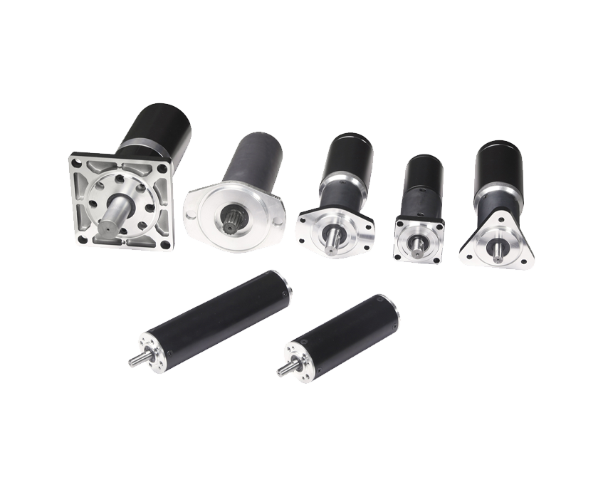
Planetary gearboxes offer the highest torque density and efficiency (typically 90–97% per stage) in a compact, coaxial form factor. They handle radial and axial shaft loads well and are the preferred choice for robotics, precision positioning, and applications needing high gear ratios in limited space. Spur gearboxes are simpler and less expensive, suitable for lighter loads where noise is less of a concern. Worm gearboxes deliver very high gear ratios in a single compact stage and provide inherent back-drive prevention — the output shaft cannot be back-driven by the load, which is useful for hoist, gate, and valve actuator applications. However, worm gearboxes have lower efficiency (40–90% depending on ratio and lead angle) and generate more heat under continuous load.
When selecting a gearbox, always verify that the gearbox's rated input speed, continuous output torque, and intermittent peak torque ratings match or exceed what the motor and application will demand. Undersized gearboxes are one of the most common causes of premature drivetrain failure in custom machine designs.
Your email address will not be published. Required fields are marked *
Tel: +86 0579-86817938-836
Phone: +86 15258922705
E-mail: [email protected]
Add: No.2 Zengping Rd., Dongyang, Zhejiang, China
You can contact to me using this form.
Copyright © Zhejiang Dongzheng Motor Co.,Ltd. All Rights Reserved.
 DC Gear Motor Manufacturers