


 English
 русский
 日本語
日本語 Español
 Deutsch
 中文简体
中文简体Product Consultation
Your email address will not be published. Required fields are marked *




DC Gear Motors Guide: Types, Applications & Selection Tips
Jul 16,2026
Worm Gear Motor Explained: Why This Compact Powerhouse Is Used Everywhere
Jul 10,2026
June birthday, growing towards the sun | The June employee birthday party of Dongzheng Electric Machinery came to a warm conclusion
Jun 05,2026Content
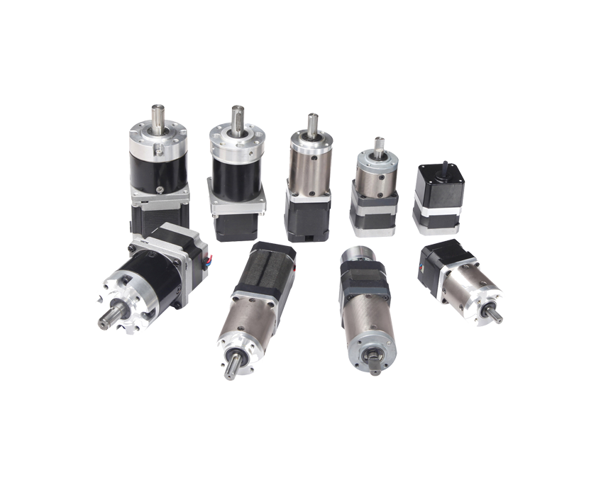
A geared stepper motor is a stepper motor combined with a mechanical gearbox — either built directly into the motor housing or mounted as a discrete reduction unit on the motor output shaft. The stepper motor itself is a brushless DC motor that moves in precise angular increments (steps) each time a current pulse is applied to its windings, providing open-loop position control without the need for an encoder or feedback device. The gearbox attached to the output shaft multiplies the motor's torque while proportionally reducing its output speed and — critically — multiplying its angular resolution, so that each electrical step of the base motor corresponds to a much smaller physical rotation of the final output shaft.
To understand why this combination is so useful, consider a standard NEMA 17 stepper motor with a 1.8° step angle (200 steps per full revolution). At full-step operation, the finest positional increment that motor can produce is 1.8°. Attach a 10:1 gearbox to that motor and the output shaft moves only 0.18° per electrical step — ten times finer positional resolution — while simultaneously delivering ten times the holding and dynamic torque of the ungeared motor (minus gearbox efficiency losses). This dual benefit of higher torque and finer resolution from the same base motor and driver is what makes geared stepper motors indispensable in precision automation, robotics, and instrumentation applications where compact size, high holding torque, and precise positioning must coexist.
The gearbox type determines the efficiency, backlash, noise level, load capacity, and physical form factor of the complete geared stepper motor assembly. Three gearbox architectures are used in commercial geared stepper motors, each suited to different application requirements.
A planetary gearbox — named for the arrangement of its gears, in which multiple "planet" gears orbit a central "sun" gear within a ring gear — is the dominant gearbox type in precision geared stepper motor applications. The load is shared simultaneously across multiple planet gears in mesh, distributing the transmitted torque across a larger total contact area than a single gear pair. This results in a very compact, high-torque-density assembly with excellent coaxial alignment between input and output shafts, low backlash (typically 1–5 arcminutes for precision grades), and high radial and axial load capacity relative to the gearbox diameter. Planetary geared stepper motors are available in standard NEMA frame sizes (NEMA 8, 11, 14, 17, 23, 34) and in gear ratios from 3.7:1 to over 100:1 through single or multi-stage configurations. They are the preferred choice for CNC systems, collaborative robots, medical devices, and any precision positioning application where backlash and load capacity are critical.
A spur gearbox uses a series of external cylindrical gears with straight cut teeth arranged in a simple gear train. Each gear pair in the train provides a stage of speed reduction and torque multiplication. Spur geared stepper motors are simpler and less expensive to manufacture than planetary versions, making them popular for cost-sensitive applications where some backlash is acceptable and radial loads on the output shaft are modest. Typical spur gear stepper motor assemblies have higher backlash than planetary equivalents (commonly 3–10° at the output shaft, depending on the number of stages and manufacturing quality) and less efficient torque transmission due to the sliding contact between straight-cut gear teeth. They are well suited to applications such as valve actuation, simple feed mechanisms, and light-duty automation where cost is prioritized over absolute precision.
A worm gearbox uses a helical worm screw (the input) meshing with a worm wheel (the output) to achieve large speed reductions in a single compact stage. Worm gear stepper motors can achieve reduction ratios of 5:1 to 100:1 in a single stage and produce a 90-degree offset between input and output shaft axes — a physical advantage in applications where right-angle drive is required. The most distinctive property of a worm gear stepper motor is self-locking: above a certain gear ratio (typically above 20:1), the worm gear cannot be back-driven by the load, meaning the output shaft holds its position mechanically without any electrical holding current. This makes worm geared stepper motors valuable for applications such as motorized gates, lifting mechanisms, and tilting platforms where power loss must not cause uncontrolled movement. The significant limitation is efficiency — worm gear friction losses are high (typically 40–80% efficiency versus 90–97% for planetary gearboxes), limiting worm gear stepper motors to lower-duty applications where heat generation and energy consumption are not critical concerns.
The table below summarizes the key performance differences between the three main gearbox types used in geared stepper motor assemblies to help in initial selection.
| Criteria | Planetary | Spur | Worm |
| Typical backlash | 1–5 arcmin (precision) | 3–10° (multi-stage) | Low–moderate |
| Efficiency | 90–97% | 85–95% | 40–80% |
| Torque density | Very high | Moderate | Moderate |
| Back-drivability | Yes | Yes | Self-locking (high ratio) |
| Shaft orientation | Coaxial (in-line) | Coaxial or offset | 90° right angle |
| Noise level | Low | Moderate | Low–moderate |
| Relative cost | Medium–High | Low–Medium | Low–Medium |
| Best use case | Precision positioning, robotics | Cost-sensitive automation | Right-angle drive, self-locking |
The gear ratio of a geared stepper motor is the single most influential specification for determining whether a given assembly will meet the requirements of an application. Understanding exactly what a gear ratio does — and does not — change about the motor system's behavior is essential for correct selection and system design.
The gear ratio N is defined as the number of input shaft revolutions required to produce one revolution of the output shaft. A gear ratio of 10:1 means the motor shaft completes ten full rotations for every one rotation of the gearbox output shaft. The torque multiplication effect is straightforward: output torque equals the motor's input torque multiplied by the gear ratio and multiplied by the gearbox efficiency (η). For a motor delivering 0.5 Nm at its shaft connected to a 10:1 planetary gearbox with 95% efficiency, the output torque is 0.5 × 10 × 0.95 = 4.75 Nm. Conversely, the output shaft speed is the motor speed divided by the gear ratio — a motor running at 600 RPM through a 10:1 gearbox delivers 60 RPM at the output. This inverse relationship between torque and speed is the fundamental mechanical trade-off that gear ratios manage.
A standard 1.8° per step stepper motor completes one revolution in 200 full steps. Through a 10:1 gearbox, the output shaft rotates 0.18° per full step, requiring 2,000 steps per output shaft revolution. Through a 50:1 gearbox, each step moves the output shaft only 0.036°, and 10,000 steps are required per revolution. This dramatic improvement in angular resolution means that very fine positioning — such as controlling the focus of a microscope objective, adjusting the angle of an antenna, or indexing a rotary table — becomes achievable with standard stepper motor hardware and a simple step-and-direction driver, without requiring microstepping or expensive servo feedback. The resolution multiplication is one of the most practically valuable attributes of geared stepper motors and is often the primary reason for selecting a geared motor over a direct-drive alternative.
A gearbox reduces the reflected inertia of the load as seen by the motor by a factor equal to the square of the gear ratio. A load with a moment of inertia of 100 kg·cm² reflected through a 10:1 gearbox appears to the motor as only 1 kg·cm² (100 / 10²). This inertia reduction is critical for achieving optimal dynamic performance — stepper motors are most responsive and least prone to stalling when the load inertia they must accelerate is close to the motor's own rotor inertia (the "inertia matching" design principle). By inserting an appropriate gearbox, a wide range of real-world load inertias can be brought into the optimal matching range for a given stepper motor, maximizing acceleration capability and step following accuracy.
Selecting a geared stepper motor requires evaluating a set of interdependent specifications that collectively determine whether the assembly will perform correctly in the target application. Focusing on only one or two parameters — such as torque and gear ratio — while ignoring others such as backlash, maximum output shaft speed, or permissible radial load leads to selection errors that are discovered only after expensive prototyping or deployment.

Geared stepper motors are deployed across an extremely broad range of automation, robotics, medical, and instrumentation applications. Their combination of precise open-loop position control, high output torque, compact form factor, and straightforward control electronics makes them uniquely well suited to a set of recurring application profiles.
Planetary geared stepper motors are used in the joints of educational robots, small collaborative robotic arms, desktop robotic manipulators, and hobby-grade articulated platforms. The high torque-to-size ratio of a planetary geared NEMA 17 or NEMA 23 stepper allows it to support and move arm segments against gravity while maintaining position without continuous current in static holds (with appropriate holding current). The elimination of feedback sensors and the associated wiring, interfaces, and tuning reduces system complexity compared to servo-based alternatives in applications where speed and absolute precision requirements are moderate. Many popular robot arm kits use NEMA 17 stepper motors with 5:1 or 10:1 planetary gearboxes on shoulder and elbow joints for exactly these reasons.
CNC rotary tables for milling and grinding use high-ratio planetary geared stepper motors to achieve the angular resolution and holding torque required for precise part indexing and continuous rotary axis contouring. A 5-axis CNC machining center's A and B rotary axes are commonly driven by worm-planetary hybrid geared stepper assemblies with gear ratios of 90:1 to 180:1, providing arc-second-level angular resolution and torque sufficient to resist cutting forces without slippage. The self-locking property of high-ratio worm gearboxes is additionally valuable here, as it prevents back-driving of the rotary axis when cutting forces are applied during machining.
Precision liquid dispensing pumps, syringe drives, peristaltic pumps, motorized microscope stages, and automated pipetting systems all rely on geared stepper motors for the combination of precise dose or positional control, compact size, and reliable open-loop operation without feedback complexity. Medical applications require geared stepper motors with cleanroom-compatible materials, low particulate generation, and in many cases biocompatible or sterilizable housing materials. Low-backlash planetary geared steppers in NEMA 8 and NEMA 11 frame sizes are the dominant choice for compact medical and laboratory instrumentation where space is severely constrained and positional accuracy of a few micrometers of linear travel (achieved through a fine-pitch leadscrew coupled to the geared stepper output) is required.
Motorized ball valves, butterfly valves, and HVAC damper actuators use geared stepper motors to drive valve elements to precise angular positions in response to building automation or process control signals. The high output torque of a geared stepper motor — often 5–50 Nm for valve actuator applications — overcomes the seating and unseating forces in process valves, while the self-holding capability of an energized stepper (or the mechanical self-locking of a high-ratio worm gear variant) maintains the valve position against fluid pressure without continuous power consumption. The simple step-and-direction control interface integrates easily with PLC and building management system (BMS) outputs.
While standard NEMA 17 stepper motors handle most axes in FDM 3D printers, geared stepper motors — particularly those with planetary gearboxes of 3:1 to 5:1 ratio — are increasingly used in the extruder drive mechanism. A geared extruder stepper provides higher grip force on the filament, better retraction control for reduced stringing, and more consistent extrusion at both low and high flow rates compared to a direct-drive ungeared motor of the same frame size. The Orbiter and Sherpa extruder designs popular in the FDM community use compact planetary geared NEMA 14 or custom-geared NEMA 17 motors specifically to achieve these extruder performance improvements in a lightweight, printhead-mountable package.
The gearbox in a geared stepper motor is a purely mechanical component — it has no electrical interface and requires no changes to the basic stepper motor driver circuit. The driver connects to the stepper motor windings in exactly the same way as for an ungeared motor, and the same step and direction signals control both. However, the gearbox introduces several practical control considerations that must be accounted for in motion system design and driver configuration.
Because the gearbox multiplies the steps-per-revolution at the output shaft by the gear ratio, the motion controller must account for this when translating a desired output shaft velocity or position into motor step commands. If the application requires the output shaft to rotate at 30 RPM through a 10:1 gearbox, the motor must rotate at 300 RPM, requiring a step rate of 300 × 200 = 60,000 steps per minute (1,000 steps per second) at full step, or proportionally higher step rates for microstepping. Most stepper motor controllers allow entry of the system's steps-per-revolution figure — which should be the motor's full-step count multiplied by the gear ratio and the microstepping factor — so that all commanded positions and velocities are specified directly in output shaft terms.
Geared stepper motors are often used in applications requiring sustained high holding torque at low output speeds, which means the motor may be energized at full rated current for extended periods. Unlike servo motors, which draw current in proportion to load, a stepper motor draws full phase current continuously whether it is moving or standing still under load. This results in continuous heat generation in the motor windings that must be managed with adequate ventilation or heat sinking. Many stepper motor drivers include an automatic current reduction feature (typically reducing current to 50–70% of running current when the motor has been stationary for 100–500 ms) which significantly reduces standby heat generation and is strongly recommended for geared stepper motor applications where the gearbox provides sufficient mechanical holding without full electrical holding current.
Stepper motors exhibit mid-frequency resonance — a speed range at which the motor's natural oscillation frequency coincides with the step excitation frequency, causing vibration, noise, and potential step loss. The gearbox partially isolates the load from motor resonance by acting as a mechanical low-pass filter: the gear mesh compliance and inertia smoothing from the gear stages attenuate the impulsive step torques before they reach the output shaft. This means that geared stepper motors often run more smoothly at resonance-prone speeds than equivalent ungeared motors driving the same load, which is an additional practical benefit beyond the primary torque and resolution advantages. Using microstepping (1/8, 1/16, or 1/32 step modes) at the driver level further reduces motor vibration and noise and is recommended for all precision geared stepper motor applications.
The decision to use a geared stepper motor versus a direct-drive stepper motor — or indeed versus a geared servo motor — should be based on a clear analysis of the application's torque, speed, resolution, accuracy, and cost requirements rather than habit or component familiarity. Each approach has a genuine performance and cost profile that favors it in certain scenarios.
Geared stepper motors are generally low-maintenance devices when correctly specified and operated within their rated parameters. The stepper motor itself is a brushless design with no commutator wear, and the ball bearings in both the motor and gearbox are designed for long service life under normal loading conditions. However, certain maintenance considerations apply over the operational lifetime of the assembly.
Your email address will not be published. Required fields are marked *
Tel: +86 0579-86817938-836
Phone: +86 15258922705
E-mail: [email protected]
Add: No.2 Zengping Rd., Dongyang, Zhejiang, China
You can contact to me using this form.
Copyright © Zhejiang Dongzheng Motor Co.,Ltd. All Rights Reserved.
 DC Gear Motor Manufacturers