


 English
 русский
 日本語
日本語 Español
 Deutsch
 中文简体
中文简体Product Consultation
Your email address will not be published. Required fields are marked *

June birthday, growing towards the sun | The June employee birthday party of Dongzheng Electric Machinery came to a warm conclusion
Jun 05,2026
Dongzheng Motor participates in the 19th (2026) International Solar Photovoltaic and Smart Energy (Shanghai) Conference and Exhibition
Jun 03,2026
Prevent through drills, prevent before it "ignites" | Dongzheng Motor's fire emergency drill concludes successfully
May 30,2026Content
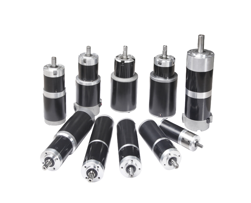
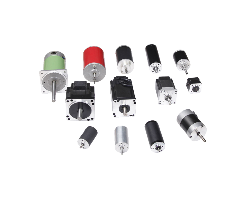
A DC spur gear motor is an integrated drive unit that pairs a direct-current electric motor with a spur gear reduction gearbox in a single compact assembly. The DC motor on its own spins fast but produces relatively low torque — useful for a fan blade, not useful for moving a conveyor belt or lifting a hatch. The spur gearbox solves that by trading rotational speed for torque through a cascade of straight-toothed gears on parallel shafts. The result is a slow-turning, high-force output shaft that can drive real mechanical loads without oversizing the motor or the power supply.
Spur gears are the simplest gear geometry in existence: cylindrical gears with teeth cut straight and parallel to the axis of rotation. One gear (the driver) meshes with the next (the driven), and power transfers at the point of tooth contact. Stack several of these pairs in series and you achieve a compound gear train — each stage multiplies torque by roughly its tooth-count ratio while dividing speed by the same factor. This multi-stage stacking is what allows DC spur gear motors to reach reduction ratios from as low as 3:1 all the way past 300:1 without exotic gear geometry.
The appeal of this design is rooted in three practical advantages: low manufacturing cost, straightforward maintenance, and high single-stage efficiency. Spur gear stages typically achieve 90–95% mechanical efficiency, meaning very little of your input power is lost to heat or friction. That makes them a reliable workhorse for applications where budget matters and torque requirements are moderate — which covers an enormous share of real-world engineering problems.
Understanding the individual parts of a DC spur gear motor tells you where performance comes from, where failure is most likely, and what to ask a supplier when specifying a unit.
The motor section converts electrical energy into rotation through electromagnetic induction. A current-carrying armature coil sits inside a stationary magnetic field produced by either permanent magnets (most common in small motors) or wound field coils (larger industrial units). The interaction between the armature current and the magnetic field generates rotational force. In a brushed DC motor, a mechanical commutator and carbon brushes switch current direction in the armature windings at precise intervals to maintain continuous rotation. The brushes physically contact the commutator rings, which is the primary wear point — brush life typically ranges from 500 to 3,000 hours depending on load and duty cycle.
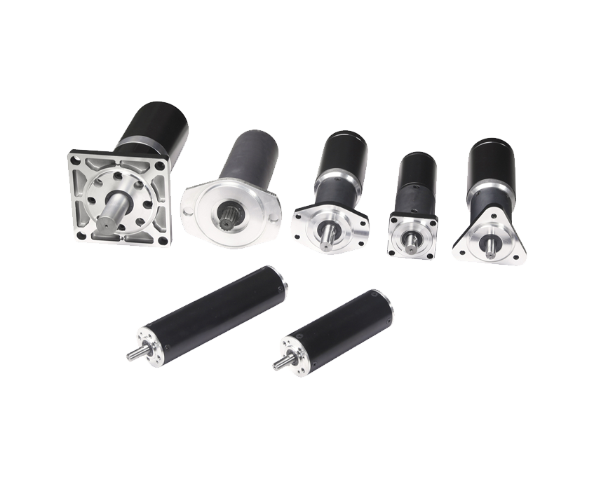
The gearbox housing encloses a series of spur gear pairs on parallel shafts. The first gear on the motor pinion shaft is small and spins fast; it drives a larger gear on the next shaft, which reduces speed and multiplies torque by the ratio of their tooth counts. Each subsequent stage repeats this process. Most DC spur gear motors use between two and five stages depending on the target output ratio. Gear materials vary: powder-metal sintered steel is common for the first one or two stages, while plastic (nylon, POM, or glass-filled nylon) is often used for later stages where torque loads are lower and noise reduction is a priority.
The output shaft is the final element — typically steel, often with a flat or D-profile keyway for coupling to driven components. Ball bearings or sleeve (sintered bronze) bearings support the output shaft; ball bearings are preferred when radial side-load is significant, while sleeve bearings suffice in low-load or intermittent duty applications. The bearing choice at the output stage strongly affects maximum side-load rating, which is one of the most commonly overlooked specs in motor selection.
Both brushed and brushless DC motors can be paired with a spur gearbox. The choice between them is one of the most consequential decisions in the selection process and should be made early — before narrowing down ratio or voltage.
| Feature | Brushed DC Spur Gear Motor | Brushless DC Spur Gear Motor |
|---|---|---|
| Control complexity | Simple — voltage or PWM signal | Requires electronic controller (ESC or driver board) |
| Efficiency | 60–80% | 85–95% |
| Service life | 500–3,000 hours (brush limited) | 10,000+ hours (no mechanical wear) |
| EMI / electrical noise | Higher — brush sparking generates noise | Lower — electronic commutation is cleaner |
| Cost | Lower upfront | 25–40% higher, but lower total cost of ownership |
| Best for | Cost-sensitive, intermittent duty, simple control | High duty cycle, precision control, medical/lab use |
For hobbyist robotics, DIY projects, and cost-sensitive consumer devices, brushed DC spur gear motors remain the default choice — they are cheaper, easier to drive with a basic H-bridge, and widely available in small form factors like the popular N20 and 130-size motor frames. For continuous industrial duty, medical equipment, or anywhere EMI is a concern, the brushless variant justifies its higher cost through reduced maintenance and longer life.
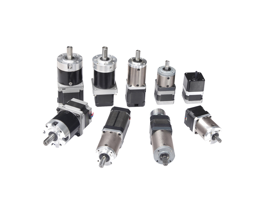
Engineers frequently debate spur versus planetary when selecting a DC gear motor. The two types are not interchangeable — each has a domain where it clearly wins, and picking the wrong one leads to either overspending or premature failure.
The core structural difference is load sharing. In a spur gear train, each gear pair carries the entire transmitted torque on its own. In a planetary arrangement, three or more planet gears share the load simultaneously around a central sun gear, which is why planetary units achieve far higher torque density in a smaller diameter. A spur gear motor is longer axially relative to its diameter; a planetary gear motor is more compact radially because load is shared — but it is mechanically more complex and costs more to manufacture.
For most applications running at moderate torque and moderate speed, a DC spur gear motor is the practical and cost-effective answer. Move into high-torque, high-speed, or precision servo applications and a planetary gear motor becomes the better choice. The table below summarizes the practical decision points:
| Decision Factor | Choose Spur | Choose Planetary |
|---|---|---|
| Budget priority | Yes — significantly cheaper | No — higher cost justified by performance |
| Output torque | Low to moderate | High torque density required |
| Backlash tolerance | Backlash acceptable | Low-backlash or positioning application |
| Noise sensitivity | Moderate — spur gears are noisier | Better at high speeds, but still noisy with spur planets |
| Axial length constraint | More axial length, smaller diameter | Shorter axially, larger diameter per stage |
| Typical application | Vending machines, toys, light conveyors | Servo axes, robotics joints, EV drives |
Motor datasheets can be intimidating at first glance, but every spec on a DC spur gear motor datasheet tells you something specific about how the motor will behave in your application. Reading them correctly prevents the most common sizing mistakes.
Most small DC spur gear motors are available in standard voltage ratings: 3V, 6V, 12V, 24V, and 48V. The rated voltage is the voltage at which the published speed, torque, and current specs were measured. Operating the motor below rated voltage reduces speed and available torque proportionally; operating it above rated voltage increases speed but also heat and current draw, shortening motor life. Most brushed motors can tolerate ±20% of rated voltage without damage, but check the datasheet before assuming.
No-load speed (free-run RPM) is how fast the output shaft spins with zero mechanical load. Rated speed (or nominal speed) is the speed at which the motor operates at its rated torque — the real working condition. These two numbers are significantly different; a motor with a 100 RPM no-load output speed might only deliver 70–80 RPM under its rated load. Always design around rated speed, not free-run speed.
Stall torque is the maximum torque the motor produces when it is completely stopped — it is also the point of maximum current draw. Operating continuously at or near stall torque will burn out the motor quickly. A practical rule of thumb: select a motor whose working torque is no more than 20–30% of its stall torque. This safety margin keeps the motor running cool and extends service life dramatically. Rated torque (the continuous safe working point) is typically listed separately and is the figure you should match to your load requirement.
The gear ratio describes how many times the motor input shaft rotates for each single rotation of the output shaft. A 100:1 ratio means the motor spins 100 times for every one output revolution — delivering 100× the motor torque (minus efficiency losses). Common DC spur gear motor ratios range from 3:1 up to 300:1. Higher ratios mean more torque and lower speed; lower ratios deliver more speed with less torque. For applications requiring very slow, powerful movement — like a valve actuator or a security camera pan drive — ratios in the 50:1 to 150:1 range are typical.
No-load current tells you how much power the motor consumes just to overcome its own internal friction and inertia. Stall current — which can be 5 to 10 times the rated operating current — determines the peak current your power supply and motor driver must handle. If your driver cannot survive the stall current (even briefly during startup), you risk driver failure. Always size your H-bridge or motor controller to handle at least the stall current of the motor it drives.

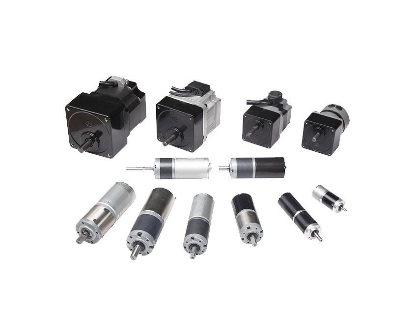
The combination of low cost, good efficiency, and straightforward mechanical output makes the DC spur gear motor one of the most broadly deployed motor types across industries. Here are the main application domains and what drives motor selection in each:
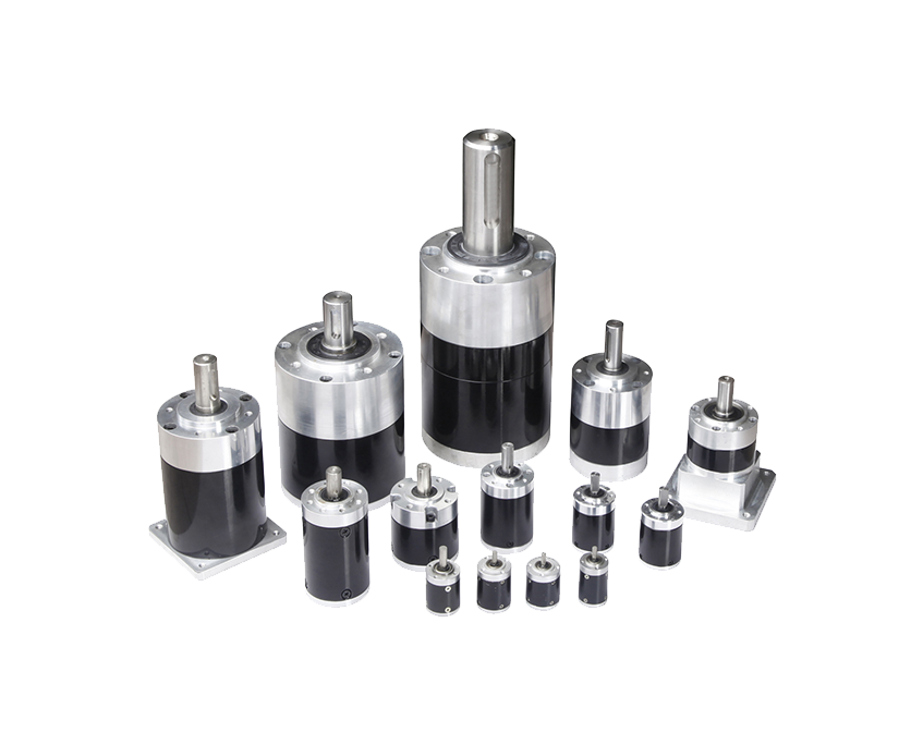
The material choice for gears inside a DC spur gear motor is not a cosmetic detail — it directly affects torque capacity, noise level, service life, and operating temperature range. Most motors use a hybrid gear train: metal for the first stages closest to the motor (where speed is highest and torque is lowest) and plastic for later stages (where torque is higher but speed is low and quieter operation is desirable).
Steel and sintered powder-metal gears handle the highest torques and operating temperatures. They are required when stall torque is expected to be significant — for example, in applications that start under load or experience shock loads. Steel gears can withstand temperatures above 100°C and are the only choice in continuous heavy-duty industrial applications. The trade-off is noise: metal-on-metal meshing generates more acoustic noise, especially at higher speeds, which is why metal gears are more acceptable in enclosed machinery than in consumer products held near the user.
Plastic gears are lighter, significantly quieter, and self-lubricating when made from POM (polyoxymethylene, also known as Delrin or Acetal). They are well suited for the later stages of a multi-stage spur gear train where torque loads are higher but peak torque demand is moderate and predictable. Nylon and POM gears fail under sustained high torque — the most common failure mode is tooth stripping at the first plastic stage. Glass-filled nylon improves load capacity but reduces the self-lubricating property, requiring appropriate grease application during assembly.
For noise-sensitive applications (medical devices, consumer products, smart home), specify motors with POM or glass-filled nylon final-stage gears. For durability and torque capacity, insist on all-metal gear trains and accept the additional noise and weight.
Motor selection mistakes are expensive — an undersized motor fails quickly, an oversized one wastes money and space, and the wrong voltage or ratio can make the entire system behave incorrectly. Work through the following steps in order.
Calculate the torque your output shaft must actually deliver to move the load. For linear loads (pulling, pushing, lifting), convert force to torque using the driven mechanism's geometry — for a wheel drive, torque = force × wheel radius. Add a service factor of at least 1.5× for applications with variable loads or infrequent starts under load. Your target rated output torque is the product of load torque × service factor.
Define your target output RPM. This is the speed at which your mechanism should operate under rated load — not the free-run speed. If you need variable speed, define the maximum operating RPM. For very slow applications (below 5 RPM), confirm the motor can regulate smoothly at low duty cycle via PWM; some brushed motors cog at very low PWM duty cycles, which is worth testing before committing to a design.
Match the motor voltage rating to your available power supply. If you are running from a lithium-ion battery pack (3.7V per cell), a 6V or 7.4V motor may be appropriate. For 12V automotive or regulated bench supplies, 12V motors offer the widest selection. Avoid running motors at significantly reduced voltages expecting to regulate torque — you lose proportional torque capacity as well as speed.
Use the formula: Gear Ratio = Motor Free-Run Speed ÷ Desired Output Speed. Then verify that the motor's rated torque at that ratio (Motor Rated Torque × Ratio × Efficiency) meets your load torque requirement with the service factor included. If no single ratio achieves both speed and torque targets, you may need to select a higher-power motor base or accept a two-stage compound gearbox.
Confirm that the motor's outer dimensions, mounting hole pattern, and output shaft diameter match your mechanical design. Standard output shaft diameters for small DC spur gear motors range from 3mm to 8mm; D-shaft and round-shaft profiles are both common. If radial side loads are high (a gear or wheel pressed onto the output shaft), verify the bearing type and rated side-load capacity — this is often the overlooked specification that causes early bearing failure.
Spur gear motors have a well-known reputation for being noisier than helical or planetary alternatives. That noise comes from two sources: the impact of gear teeth engaging and disengaging at the mesh point, and electromagnetic noise from the motor commutator. Both can be reduced significantly with the right design choices.
DC spur gear motors are generally low-maintenance, but they are not zero-maintenance. Knowing where they typically fail lets you design more durable systems and catch problems before they cause unplanned downtime.
This is the primary wear mechanism in brushed DC spur gear motors. Carbon brushes erode gradually and deposit carbon dust inside the motor housing. Over time, brush length decreases until contact pressure drops and commutation becomes erratic — the symptom is intermittent operation, increased current draw, and visible sparking at the commutator. In accessible motors, brushes can be inspected and replaced; in sealed consumer units, brush wear usually means end-of-life replacement of the full motor assembly.
The first plastic gear stage (immediately after the motor pinion) is the most common mechanical failure point. Overloading — running the motor at torques exceeding 30% of stall torque continuously, or encountering sudden jams — causes plastic gear teeth to shear or strip. This failure is instantaneous and catastrophic for the drivetrain. The fix is application-level: add a torque-limiting clutch upstream of the gearbox, or select a motor with a higher stall torque to maintain the recommended 30% working torque margin.
Side-load-induced bearing failure appears as wobble on the output shaft, increased friction, and eventually seizure. It is most common when a gear, pulley, or wheel is mounted directly on the output shaft without an external bearing block. Verify the motor's rated radial load (usually specified at 5mm from the bearing face) and add a support bearing in the mechanical design if the load exceeds this figure.
Factory-applied grease inside a DC spur gear motor does not last forever, especially in high-temperature environments or applications running more than 8 hours per day. Grease that has dried out or been chemically degraded by incompatible solvents loses its viscosity, accelerating gear and bearing wear. In accessible gear trains, annual regrease with the correct lubricant type (synthetic for plastic gears, lithium-based for metal-only trains) extends service life considerably.
Your email address will not be published. Required fields are marked *
Copyright © Zhejiang Dongzheng Motor Co.,Ltd. All Rights Reserved.
 DC Gear Motor Manufacturers